Airborne Magnetic Compensation Method Including Compensation of Orientation Error of Multi-Optical System Atomic Magnetometer

An atomic magnetometer and directional error technology, which is applied in the directions of instruments, surveying and navigation, measuring devices, etc., can solve problems such as affecting the performance index of magnetic compensation, inaccurate solution of T-L model coefficients, and directional error of optical pump atomic magnetometers.

Active Publication Date: 2020-10-09
PEKING UNIV
View PDF8 Cites 0 Cited by
  • Summary
  • Abstract
  • Description
  • Claims
  • Application Information

AI Technical Summary

Problems solved by technology

[0008] Due to the existence of the direction error of the optically pumped atomic magnetometer, when the aircraft maneuvers during the calibration flight, the total magnetic field measured by the optically pumped atomic magnetometer introduces additional magnetic field errors, which leads to inaccurate solutions of the T-L model coefficients and affects magnetic compensation. performance indicators

Method used


Image

  • Airborne Magnetic Compensation Method Including Compensation of Orientation Error of Multi-Optical System Atomic Magnetometer
  • Airborne Magnetic Compensation Method Including Compensation of Orientation Error of Multi-Optical System Atomic Magnetometer
  • Airborne Magnetic Compensation Method Including Compensation of Orientation Error of Multi-Optical System Atomic Magnetometer

Examples


Embodiment Construction

[0077] Below in conjunction with accompanying drawing and embodiment the present invention is described in further detail, it is necessary to point out here that the following specific embodiments are only used to further illustrate the present invention, can not be interpreted as limiting the protection scope of the present invention, those of ordinary skill in the art Some non-essential improvements and adjustments can be made to the present invention based on the above-mentioned content of the invention.

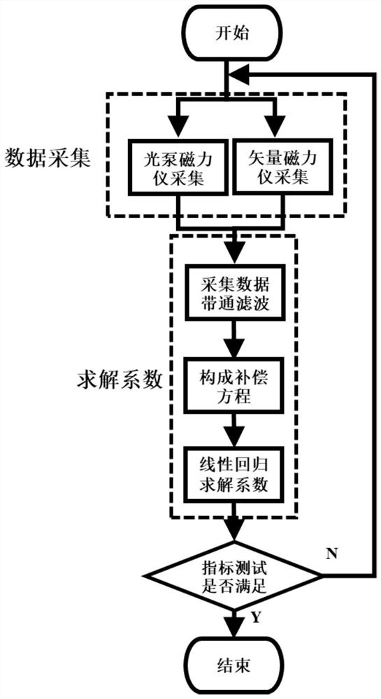
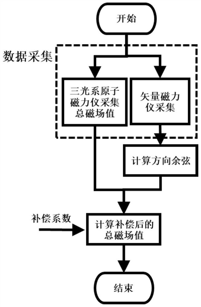
[0078] The invention provides an aeromagnetic compensation method. By establishing an aeromagnetic compensation model including an optically pumped multi-optical system atomic magnetometer direction error compensation model, the vector magnetometer measures data and calculates the direction cosine to perform real-time aeromagnetic compensation. Simultaneously compensate the direction error of the multi-optical system optical pump atomic magnetometer and the aircraft's mane...


PUM


Abstract

The invention discloses an aeromagnetic compensation method. An aeromagnetic compensation model including a multi-light-system optical pump atomic magnetometer direction error compensation model is established; a direction cosine is calculated based on vector magnetometer measurement data; real-time aeromagnetic compensation is performed; and multi-light-system atomic magnetometer direction error and aircraft maneuvering magnetic interference are compensated simultaneously. According to the invention, the model can be combined with a classical aeromagnetic compensation model T-L model and the aeromagnetic compensation model including the multi-light-system optical pump atomic magnetometer direction error compensation is established; linear regression is performed on aircraft magnetic interference and optical pump atomic magnetometer direction error compensation to obtain a total coefficient; and real-time compensation is performed. According to the invention, the direction errors of the aircraft magnetic interference and the optical pump atomic magnetometer can be compensated simultaneously, so that the accuracy of the T-L model coefficient obtained by the aeromagnetic compensation is enhanced and thus the aeromagnetic detection capability is improved.

Description

technical field [0001] The invention belongs to the technical field of optical pump atomic magnetometer and aeronautical magnetic detection, and relates to an aeromagnetic compensation algorithm including multi-light system atomic magnetometer direction error compensation. The method can simultaneously compensate multi-light system atomic magnetometer direction error and aircraft maneuvering Magnetic interference, thereby improving the ability of airborne magnetic detection. Background technique [0002] Magnetometer is a general term for instruments that measure the size of the external magnetic field, and is widely used in the fields of geophysics, space exploration, biomedicine, and military defense. Magnetometers can be classified into scalar magnetometers (which measure scalar total magnetic field information) and vector magnetometers (which measure the three perpendicular components of the magnetic field). Airborne magnetic detection usually uses a scalar magnetometer...

Claims


Application Information

Patent Timeline
Patent Type & Authority Patents(China)
IPC IPC(8): G01C17/38
CPCG01C17/38
Inventor 郭弘彭翔王贺王海东都长平刘洋
Owner PEKING UNIV
Why Eureka
Try Eureka