Mechanical vibrating device used in concrete test process

A technology of test process and vibrating device, which is applied in the preparation of test samples, measuring device, sampling, etc., can solve the problems of concrete test block defects and physical exertion, and achieve the effect of saving manpower, uniform vibrating and high strength

Active Publication Date: 2019-09-24
山西嬴康祖混凝土有限公司
View PDF3 Cites 4 Cited by
  • Summary
  • Abstract
  • Description
  • Claims
  • Application Information

AI Technical Summary

Problems solved by technology

[0003] In the actual construction process, in order to determine the mix ratio of concrete, that is, the specific ratio of cement, sand, stones and some admixtures, it is necessary to conduct experiments in the laboratory first, that is, to make concrete test blocks through different mix ratios, and then test the concrete Test the compressive strength of the test block, so as to determine the best mix ratio according to the strength value. In the process of concrete forming, first mix cement, sand, stone and some admixtures with water, and then mix the concrete Put it into the mold, and then use the vibrating rod to insert and pull out repeatedly inside the concrete, so as to vibrate and compact the concrete. However, in the actual process, people hold the vibrating rod to repeatedly insert and pull out in the concrete mold , it takes a lot of physical strength, and for female experimenters with less strength, it is obvious that the insertion depth of the vibrating rod is not enough due to insufficient strength, resulting in incomplete filling of the corners at the bottom of the mold, resulting in defects in the concrete test block

Method used


Image

  • Mechanical vibrating device used in concrete test process
  • Mechanical vibrating device used in concrete test process

Examples


Embodiment Construction

[0019] The following will clearly and completely describe the technical solutions in the embodiments of the present invention with reference to the accompanying drawings in the embodiments of the present invention. Obviously, the described embodiments are only some, not all, embodiments of the present invention. Based on the embodiments of the present invention, all other embodiments obtained by persons of ordinary skill in the art without making creative efforts belong to the protection scope of the present invention.

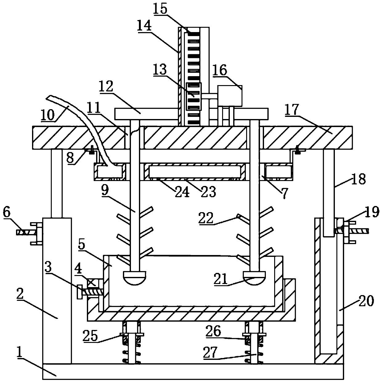
[0020] see Figure 1 to Figure 2 , the present invention provides a technical solution: a mechanical vibrating device used in a concrete test process, comprising a base 1, a supporting square tube 2, a rectangular tank 4, a mold 5, a vibrating rod 9, a top plate 17, and a movable rod 18 , hoisting device and damping device, the four corners of the upper surface of the base 1 are fixedly provided with a support square tube 2, the inside of the support square tu...


PUM


Abstract

The invention discloses a mechanical vibrating device used in a concrete test process, comprising a base, support square tubes, a rectangular trough body, a lifting device and a damping device, wherein the support square tubes are fixedly disposed at the four corners of the upper surface of the base; movable rods are inserted into the support square tubes; screws are fixedly disposed on the outer sides of the bottoms of the movable rods; end portions of the screws extend out of rectangular through grooves outside the support square tubes; and the screws are provided with stopping nuts outside the support square tubes. In actual use, a mold filled with concrete can be placed inside the rectangular tank body and then is fixed by fastening screws, then the insertion depths of the movable rods in the support square tube are adjusted so that a vibration needle is located at a suitable height inside the mold; then the lifting device is activated to move the vibration needle up and down to tamp the concrete in the mold. The mechanical vibrating device avoids manual repeat tamp and saves manpower.

Description

technical field [0001] The invention relates to the technical field of a mechanical vibration device used in a concrete test process, in particular to a mechanical vibration device used in a concrete test process. Background technique [0002] Concrete is a mixture of cement, sand, stones, and some admixtures. [0003] In the actual construction process, in order to determine the mix ratio of concrete, that is, the specific ratio of cement, sand, stones and some admixtures, it is necessary to conduct experiments in the laboratory first, that is, to make concrete test blocks through different mix ratios, and then test the concrete Test the compressive strength of the test block, so as to determine the best mix ratio according to the strength value. In the process of concrete forming, first mix cement, sand, stone and some admixtures with water, and then mix the concrete Put it into the mold, and then use the vibrating rod to insert and pull out repeatedly inside the concrete...

Claims


Application Information

Patent Timeline
Patent Type & Authority Applications(China)
IPC IPC(8): G01N1/28G01N1/36
CPCG01N1/286G01N1/36G01N2001/366
Inventor 王亚军
Owner 山西嬴康祖混凝土有限公司
Why Eureka
Try Eureka