Explosion-proof switch cabinet and explosion-proof method of switch cabinet

An explosion-proof switch and cabinet technology, applied in the field of switch cabinets, can solve the problems of high explosion-proof pressure and the explosion-proof effect needs to be improved, and achieve the effects of slowing down the rising rate, reducing the pressure rising rate and reducing the explosion scale.

Pending Publication Date: 2019-09-24
四川电器集团股份有限公司
View PDF7 Cites 0 Cited by
  • Summary
  • Abstract
  • Description
  • Claims
  • Application Information

AI Technical Summary

Problems solved by technology

[0005] The object of the present invention is to provide an explosion-proof switchgear and an explosion-proof method for the switchgear, so as to solve the problems in the prior art that the switchgear has high explosion-proof pressure and the explosion-proof effect needs to be improved, and realize the purpose of improving the explosion-proof capability of the switchgear

Method used


Image

  • Explosion-proof switch cabinet and explosion-proof method of switch cabinet
  • Explosion-proof switch cabinet and explosion-proof method of switch cabinet
  • Explosion-proof switch cabinet and explosion-proof method of switch cabinet

Examples


Embodiment 1

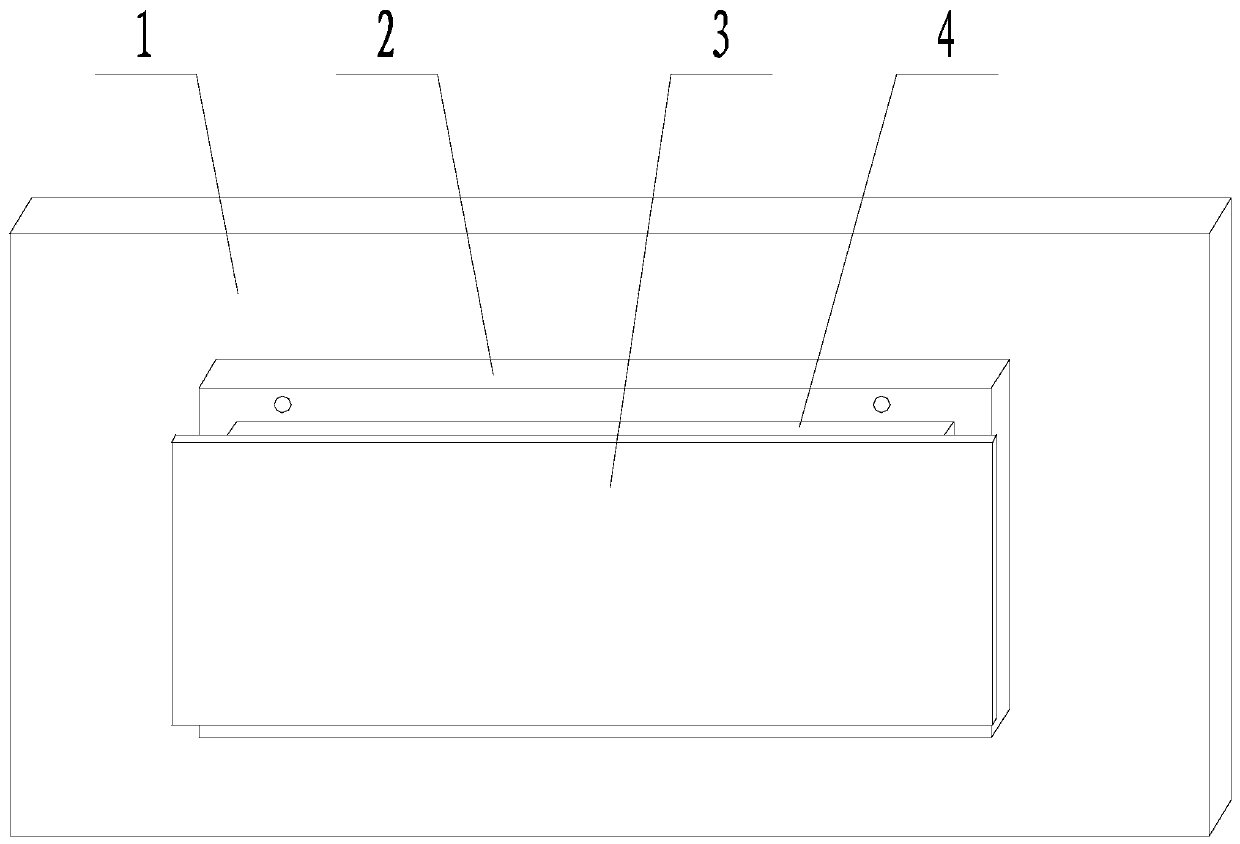
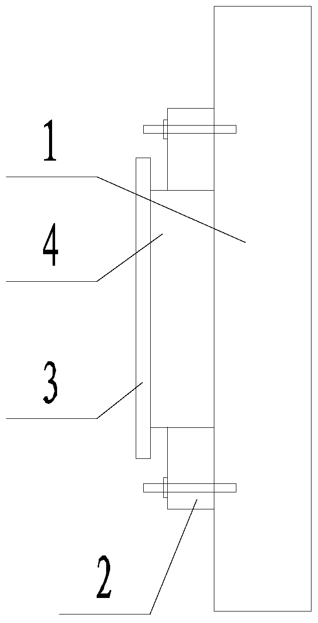
[0033] like figure 1 and figure 2The shown explosion-proof switch cabinet includes a cabinet body 1 and an energy absorbing device fixed on the inner wall of the cabinet body 1. The energy absorbing device includes a frame 2, a partition 3, and foamed aluminum 4. The frame 2 is fixed On the inner wall of the cabinet body 1, the outer profile of the foamed aluminum 4 matches the inner profile of the frame 2, and the foamed aluminum 4 is stuffed into the frame 2, wherein the thickness of the foamed aluminum 4 is greater than that of the frame 2 Thickness; the partition 3 is fixed on the side surface of the foamed aluminum 4 facing the inside of the cabinet body 1 .

[0034] When the switchgear is working normally, the energy absorbing device will not cause any interference to the switchgear in the cabinet. When the temperature inside the cabinet rises and the pressure rises rapidly, the increased air pressure will act on the foamed aluminum, and the foamed aluminum will Under...

Embodiment 2

[0036] On the basis of Example 1, one side surface of the foamed aluminum 4 is attached to the inner wall of the cabinet body 1, and the other side surface is attached to the partition 3; the projection of the foamed aluminum 4 on the surface of the partition 3 is completely Fall into the area where the partition 3 is located. The separator 3 is a galvanized steel plate. The energy absorbing device is fixed on the inner side wall of the cabinet body 1 and the inner side surface of the cabinet door of the cabinet body 1 . The foamed aluminum 4 is soldered to the separator 3 or bonded by an adhesive. In the brazing connection process, it is necessary to use a vacuum welding process or a nitrogen protection process, and use Al-Si solder as an intermediate layer. After the welding is completed, the temperature is kept at 585-600° C. for 5-15 minutes. In this embodiment, the frame 2 and the cabinet body 1 are fixedly connected by bolts.

[0037] The performance of the aluminum f...

Embodiment 3

[0045] On the basis of any of the above-mentioned embodiments:

[0046] preferred, such as Figure 4 As shown, the partition 3 extends as a cover covering the inner wall of the cabinet body 1 .

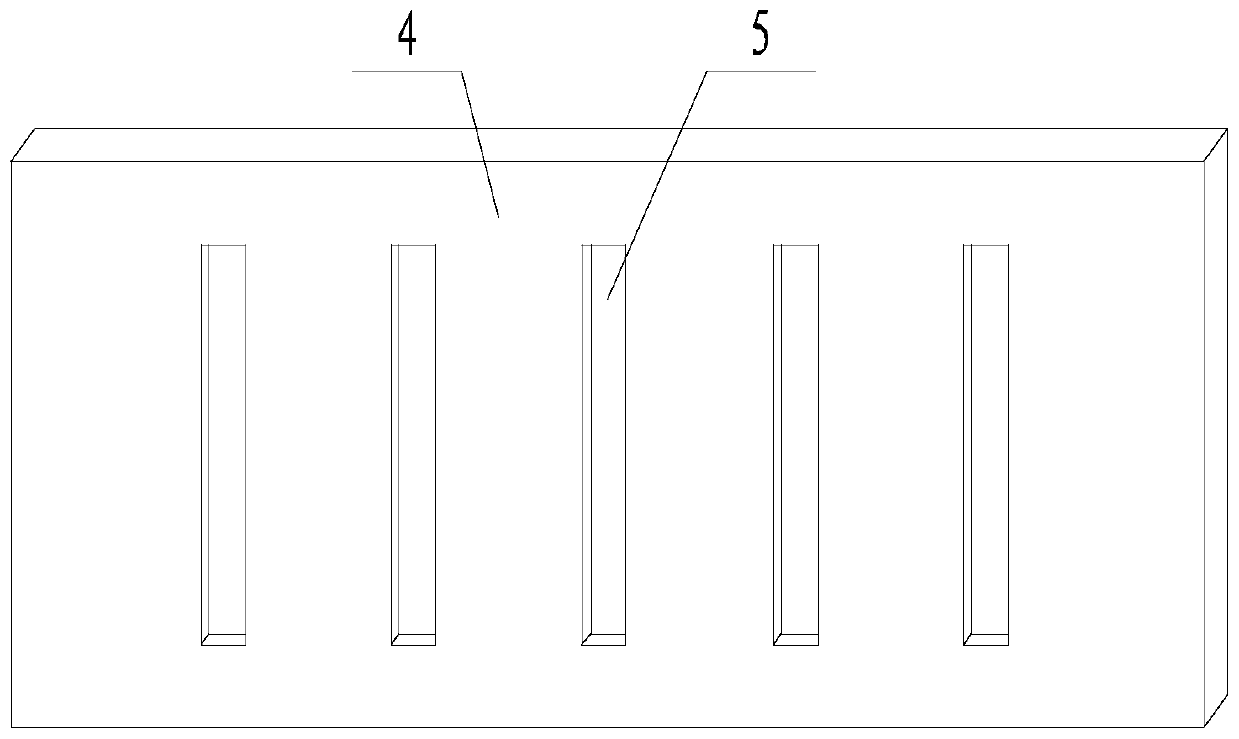
[0047] preferred, such as image 3 As shown, the foamed aluminum 4 is provided with a plurality of parallel grooves 5 on one side surface facing the inside of the cabinet body 1 .


PUM

PropertyMeasurementUnit
thermal conductivityaaaaaaaaaa
porosityaaaaaaaaaa
porosityaaaaaaaaaa

Abstract

The invention discloses an explosion-proof switch cabinet and an explosion-proof method of the switch cabinet. The cabinet comprises a cabinet body and further comprises an energy absorption device fixed to the inner wall of the cabinet body. The energy absorption device comprises a frame, a partition plate and foamed aluminum, wherein the frame is fixed to the inner wall of the cabinet body, the outline of the foamed aluminum is matched with the outline of the frame, the foamed aluminum fills the frame, and the thickness of the foamed aluminum is greater than that of the frame. The partition plate is fixed to the surface of the side, facing the interior of the cabinet body, of the foamed aluminum. The invention aims to provide the explosion-proof switch cabinet and the explosion-proof method of the switch cabinet so as to solve the problems that the explosion-proof pressure of the switch cabinet is large and the explosion-proof effect needs to be improved in the prior art and achieve the purpose of improving the explosion-proof capability of the switch cabinet.

Description

technical field [0001] The invention relates to the field of switch cabinets, in particular to an explosion-proof switch cabinet and an explosion-proof method for the switch cabinet. Background technique [0002] The switch cabinet is a kind of electrical equipment. The external line of the switch cabinet first enters the main control switch in the cabinet, and then enters the sub-control switch, and each branch is set according to its needs. Such as instruments, automatic controls, motor magnetic switches, various AC contactors, etc., some also have high-voltage room and low-voltage room switch cabinets, high-voltage busbars, such as power plants, etc. load shedding. The main function of switchgear is to switch, control and protect electrical equipment during the process of power generation, transmission, distribution and power conversion in the power system. The components in the switch cabinet are mainly composed of circuit breakers, disconnectors, load switches, operat...

Claims


Application Information

Patent Timeline
Patent Type & Authority Applications(China)
IPC IPC(8): H02B1/30H02B3/00B32B5/18B32B37/12B32B7/12B32B37/00
CPCH02B1/30H02B3/00B32B5/18B32B37/12B32B7/12B32B37/00B32B2266/045
Inventor 刘叔元何周富代安东王丽杰邓丹
Owner 四川电器集团股份有限公司
Why Eureka
Try Eureka