Fault current relief device and power system with overvoltage protection

A fault current and overvoltage technology, applied in the field of power system, can solve the problems of bleeder resistor burning, line overvoltage protection setting influence, loss, etc., to reduce investment cost, safe and efficient removal, and reduce breaking pressure.

Active Publication Date: 2020-12-01
HUNAN UNIV
View PDF3 Cites 0 Cited by
  • Summary
  • Abstract
  • Description
  • Claims
  • Application Information

AI Technical Summary

Problems solved by technology

When the FCL is connected in series in the line, the closing and breaking conditions of the circuit breaker may be more stringent;
[0005] 3) FCL will affect the automatic reclosing of the circuit breaker;
[0006] 4) The current-limiting reactance of FCL is connected in series to the line to suppress the short-circuit current, but it also affects the setting of the line overvoltage protection
When the power grid fails, if it cannot be dealt with in time, it may further expand the scope of the accident and cause greater losses
[0014] At the same time, this scheme does not consider the countermeasures that the bleeder bears more than its own short-circuit current
The bleeder resistor has its own threshold value that can bleed the maximum fault current. If this value is exceeded, the bleeder resistor will burn out and cause the bleeder to fail.

Method used


Image

  • Fault current relief device and power system with overvoltage protection
  • Fault current relief device and power system with overvoltage protection
  • Fault current relief device and power system with overvoltage protection

Examples


Embodiment 1

[0042] Figure 4 It is a structural schematic diagram of a fault current leakage device with overvoltage protection according to an embodiment of the present invention.

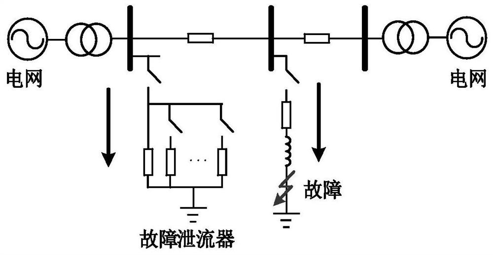
[0043] Such as Figure 4 As shown, the fault current leakage device with overvoltage protection includes: a current collector 10 , a fault current leakage device 20 and a controller 30 .

[0044] Among them, see Figure 4 , the current collector 10 is used to collect the current of the transmission line L; the fault current collector 20 includes a controllable switch K, a discharge circuit 21 and a protection circuit 22, one end of the controllable switch K is connected with the transmission line L, and the discharge circuit 21 One end of the controllable switch K is connected to the other end of the controllable switch K, the other end of the discharge circuit 21 is grounded, and the protection circuit 22 is connected in parallel with the discharge circuit 21, and the protection circuit 22 is used when the...

Embodiment 2

[0059] Figure 9 It is a structural block diagram of the power system of the embodiment of the present invention.

[0060] Such as Figure 9 As shown, the power system 1000 includes the fault current leakage device 100 with overvoltage protection according to the above-mentioned embodiments of the present invention.

[0061] The power system of the embodiment of the present invention adopts the above-mentioned fault current discharge device with overvoltage protection, and uses the discharge resistor to divide the large fault current into multiple small fault currents, so as to reduce the breaking pressure of the fault branch circuit breaker, It can ensure that the fault can be removed safely and efficiently, and can ensure the safety of the leakage circuit itself. At the same time, it can effectively reduce the design capacity of electrical equipment such as circuit breakers, transformers, and transformers, and reduce investment costs.

[0062] In the description of the pre...


PUM


Abstract

The invention discloses a fault current discharge device with overvoltage protection and a power system, wherein the fault current discharge device includes: a current collector for collecting the current of a power transmission line; a fault current release device, a fault current release device It includes a controllable switch, a discharge circuit and a protection circuit. One end of the controllable switch is connected to the transmission line, the other end is connected to one end of the discharge circuit, the other end of the discharge circuit is grounded, and the protection circuit is connected in parallel with the discharge circuit. When the voltage at both ends of the leakage circuit is greater than the preset voltage threshold, the protection action is performed; the controller is connected to the control terminal of the current collector and the controllable switch respectively, and is used for when the current of the transmission line is greater than the preset current threshold , to control the controllable switch to close, so that the leakage circuit performs the leakage work. The fault current discharge device with overvoltage protection can not only ensure that the fault can be removed safely and efficiently, but also ensure the safety of the discharge circuit itself.

Description

technical field [0001] The invention relates to the technical field of power systems, in particular to a fault current discharge device with overvoltage protection and a power system. Background technique [0002] With the development of my country's social economy, the power load has increased rapidly, the scale of the power grid has expanded rapidly, and the interconnection between regional power grids has become increasingly close. Although the rapid development of the power grid has greatly improved the power transmission capacity of the line, it has also led to a rapid increase in the short-circuit current level of the system. The short-circuit current has great harm to the safe and stable operation of the power system and the electrical equipment itself. Excessive short-circuit current may exceed the interrupting capacity of the circuit breaker, making it difficult to remove the fault in time. How to limit the short-circuit current in power system faults has always a...

Claims


Application Information

Patent Timeline
Patent Type & Authority Patents(China)
IPC IPC(8): H02H9/04H02H9/06G01R31/52G01R19/165
CPCH02H9/041H02H9/06G01R19/16576G01R31/50
Inventor 黎灿兵张辽刘绪斌周斌
Owner HUNAN UNIV
Why Eureka
Try Eureka