
Camera-based contactless pulse rate measurement method and device

A non-contact, camera technology, applied in the field of computer image and vision, can solve the problems of difficulty and accuracy, inconvenient use, high price of instruments and equipment, and achieve the effect of saving construction costs.

Active Publication Date: 2019-09-27
上海星图金融服务集团有限公司
View PDF22 Cites 1 Cited by
  • Summary
  • Abstract
  • Description
  • Claims
  • Application Information

AI Technical Summary

Problems solved by technology

However, this method needs to place electrodes on the person under test, requires special instruments and venues, is not flexible enough and the price of the instruments and equipment is high, and it is difficult for ordinary consumers to apply; the photoplethysmography (PPG) method is measured with the help of photoelectric It is a non-invasive detection method that detects changes in blood volume in living tissue. Common sports bracelets on the market use this method to measure pulse rate, but in practical applications, such as running, sports bracelet wearers usually do not like Tighten the wristband, which will cause dynamic changes in the angle and angle between the photoelectric sensor and the user's skin, which will greatly affect the accuracy of the measurement. Therefore, measurement errors are common in the current sports bracelets on the market. It can only be used to roughly represent the change trend of heart rate, and it is difficult to apply to scenes with higher accuracy requirements
[0005] Moreover, both of these two pulse rate measurement methods require sensors (electrodes or PPG photosensitive sensors) to be placed on the skin surface of the subject, that is, the measuring instrument needs to be very close to or in contact with the subject, and the problem of inconvenient use cannot be solved.

Method used


Image

  • Camera-based contactless pulse rate measurement method and device
  • Camera-based contactless pulse rate measurement method and device
  • Camera-based contactless pulse rate measurement method and device

Examples


Embodiment Construction

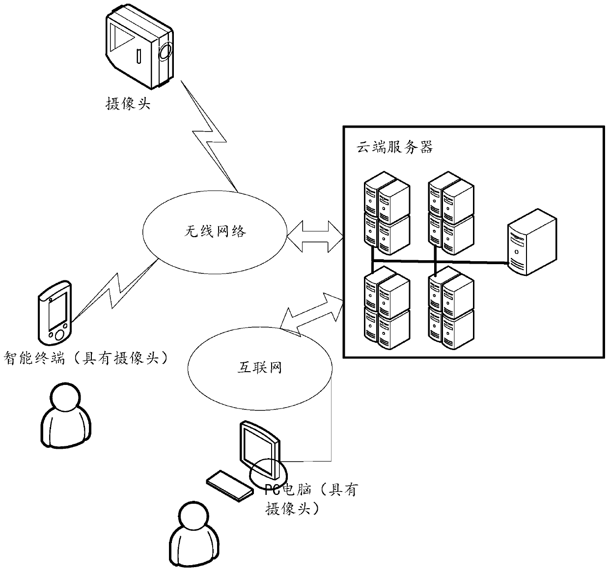
[0020] In order to enable those skilled in the art to better understand the technical solution of the present invention, the present invention will be described in further detail below in conjunction with the accompanying drawings and specific embodiments. Hereinafter, embodiments of the present invention will be described in detail, examples of which are shown in the accompanying drawings, wherein the same or similar reference numerals denote the same or similar elements or elements having the same or similar functions throughout. The embodiments described below by referring to the figures are exemplary only for explaining the present invention and should not be construed as limiting the present invention. Those skilled in the art will understand that the singular forms "a", "an", "said" and "the" used herein may also include plural forms unless otherwise stated. It should be further understood that the word "comprising" used in the description of the present invention refers...


PUM


Abstract

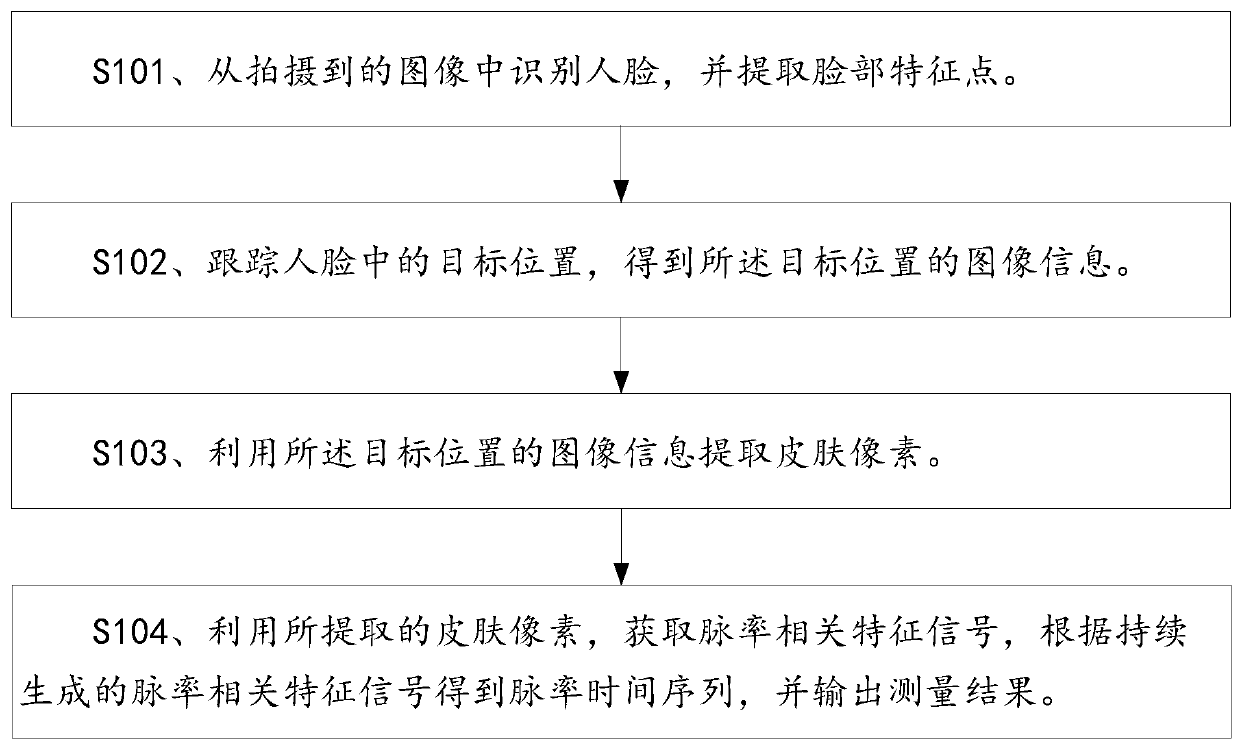
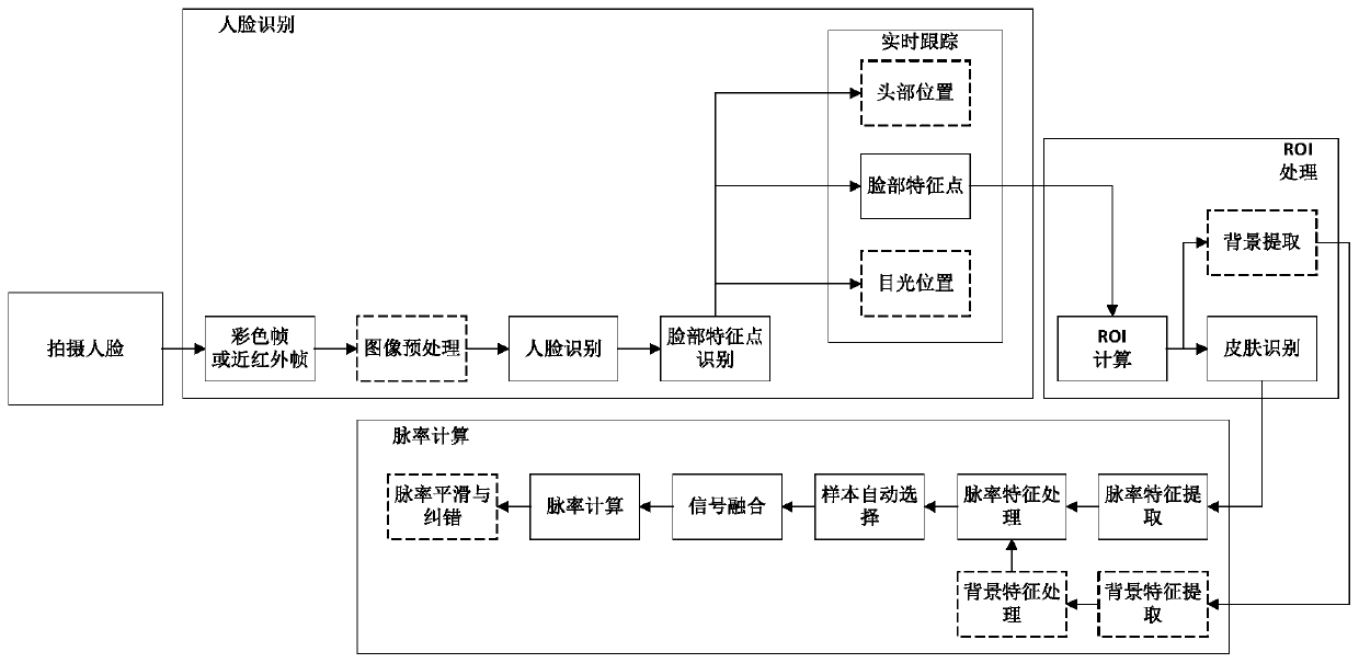
An embodiment of the invention discloses a camera-based contactless pulse rate measurement method and device, and relates to the technical field of computer images and vision. By means of the method and the device, contactless remote measurement of human body sign signals (pulse rates) can be realized. The method comprises the following steps: recognizing a human face from a shot image and extracting a facial feature point; tracking a target position in the human face to obtain image information of the target position, wherein the target position comprises the position of the facial feature point; extracting a skin pixel according to the image information of the target position; acquiring a pulse rate related characteristic signal according to the extracted skin pixel, obtaining a pulse rate time sequence according to the continuously generated pulse rate related characteristic signal, and outputting a measurement result. The method and the device are suitable for contactless measurement of human body sign signals.

Description

technical field [0001] The present invention relates to the field of computer image and visual technology, in particular to a non-contact pulse rate measurement method and device based on a camera. Background technique [0002] At present, non-contact detection of human body sign characteristic signals, such as pulse rate (heartbeat) measurement, is one of the scientific and technological research directions in academia and industry. Obtaining human heartbeats through non-contact has a wide range of business needs and commercial values ​​in the fields of medical care, finance, and transportation. [0003] In the industry, pulse rate measurement is usually done by means of electrocardiogram (ECG) and photoplethysmography (PPG), among which: [0004] Electrocardiogram (ECG) measurement is the most mature pulse rate measurement method at the medical device level. However, this method needs to place electrodes on the person under test, requires special instruments and venues, ...

Claims


Application Information

Patent Timeline
IPC IPC(8): A61B5/024G06K9/00
CPCA61B5/024A61B5/72G06V40/172
Inventor 王元
Owner 上海星图金融服务集团有限公司
Learn More