
Rotary distance adjusting device

An adjusting device and rotary technology, applied in grain processing, application, grain pod removal, etc., can solve the problems of inaccurate adjustment accuracy, unstable pressure, high processing cost, reduce follow-up work, stabilize distance, and avoid broken rice effect of the phenomenon

Pending Publication Date: 2019-09-27
SATAKE MFG SUZHOU
View PDF0 Cites 2 Cited by
  • Summary
  • Abstract
  • Description
  • Claims
  • Application Information

AI Technical Summary

Problems solved by technology

However, the processing accuracy of the planar rice cutter adjustment device is high, the processing cost is high, and the cost of later replacement is high; and when performing maintenance and replacement, the hopper on the top of the emery roller rice machine must be raised, which requires the joint efforts of multiple people to move it. The straight and flat rice knife is removed from the machine, and then the whole device is disassembled and the rice knife is replaced. After the replacement is completed, it is reinstalled on the machine. The whole process is time-consuming and labor-intensive.
In addition, the installation and adjustment of straight and flat rice knives need to keep a straight line up and down. The straightness adjustment operation of the rice knife plane requires high requirements, but human factors are not easy to control, which makes it easy for the rice knife to tilt up and down, resulting in a gap between the rice knife and the grinding wheel. The gap between them is different up and down, which makes the internal pressure of the raw materials unstable, which will have a great impact on the grinding effect, resulting in more broken rice, increasing the broken rice rate in the finished product, and aggravating the subsequent processing. Ability; the adjustment accuracy is not accurate, and sometimes it needs to be adjusted back and forth multiple times to achieve the required distance

Method used


Image

  • Rotary distance adjusting device
  • Rotary distance adjusting device

Examples


Embodiment Construction

[0015] The following specific examples illustrate the implementation of the present invention. Those skilled in the art can easily understand other advantages and effects of the present invention from the content disclosed in this specification.

[0016] See Figure 1 to Figure 2 It should be noted that the structure, ratio, size, etc. shown in the accompanying drawings in this specification are only used to match the content disclosed in the specification for the understanding and reading of those familiar with this technology, and are not intended to limit the implementation of the present invention Limited conditions, so it has no technical significance. Any structural modification, proportional relationship change or size adjustment should still fall under the present invention without affecting the effects and objectives that can be achieved by the present invention. The disclosed technical content must be within the scope of coverage. At the same time, the terms such as "u...


PUM


Abstract

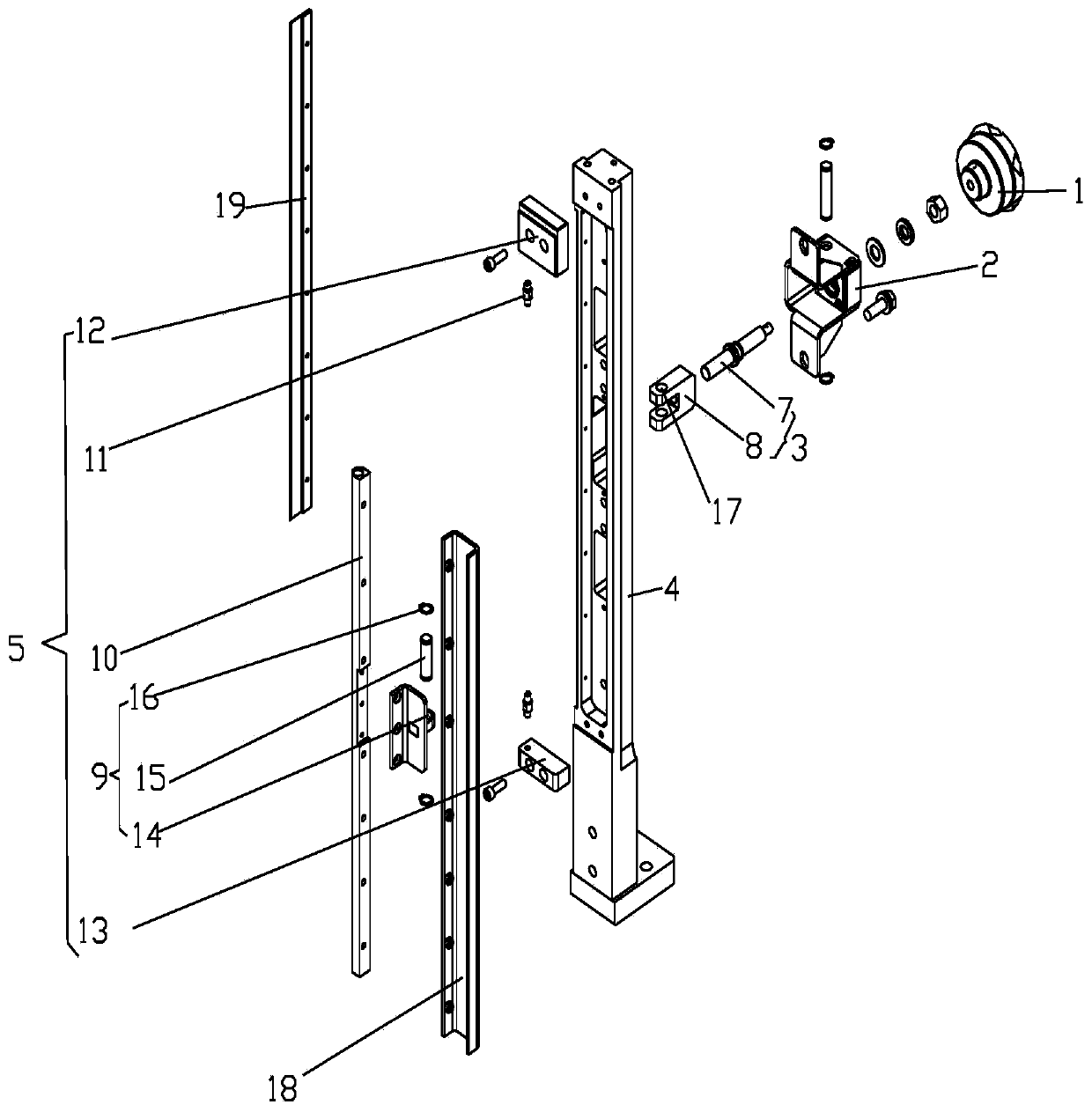
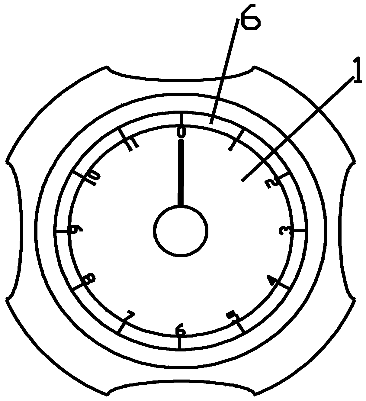
The invention relates to a rotary distance adjusting device. The device comprises an adjusting handle, a handle fixing base, a distance adjusting module, a frame and a rotating module; the adjusting handle penetrates through the handle fixing base to be connected with the distance adjusting module, the distance adjusting module penetrates through the frame to be connected with the rotating module, and the rotating module comprises a connector, a rotating shaft, pins, an upper pressing plate and a lower pressing plate; the connector is connected with the middle of the rotating shaft, the two ends of the rotating shaft are connected with the upper pressing plate and the lower pressing plate through the pins respectively, the upper pressing plate is connected with the upper part of the frame, and the lower pressing plate is connected with the lower part of the frame. The rotary distance adjusting device achieves the purpose of precisely adjusting the distance through the distance adjusting module, ensures the consistency of the vertical spacing between a rice cutter and a grinding wheel, and reduces the rice damage rate of a finished product.

Description

Technical field [0001] The invention relates to a rotary distance adjustment device, and relates to the field of distance adjustment of rice knives. Background technique [0002] The vertical emery roller rice machine mainly achieves the whitening effect through the grinding between the raw material and the grinding wheel, rice knife, and screen. The degree of whitening can be achieved by adjusting the gap between the rice knife and the grinding wheel. At present, most of the vertical emery roll rice machines at home and abroad use a flat rice knife adjusting device. The distance between the rice knife and the grinding wheel is adjusted by positioning bolts to adjust the internal pressure of the rice mill. However, the flat rice knife adjustment device requires high processing accuracy, high processing cost, and high cost of later replacement; and when maintenance and replacement are performed, the top silo of the emery roll rice machine must be raised. It requires multiple peop...

Claims


Application Information

Patent Timeline
Patent Type & Authority Applications(China)
IPC IPC(8): B02B3/00B02B7/00
CPCB02B3/00B02B7/00
Inventor 谈菊红贺为群
Owner SATAKE MFG SUZHOU
Learn More