Construction method of a steel bar bending device

A steel bar bending and construction method technology, applied in the field of steel bar engineering technology construction, to achieve the effect of increasing the force arm, saving force, and enhancing the integrity

Active Publication Date: 2021-02-12
BEIJING LIUJIAN CONSTR GRP +1
View PDF7 Cites 0 Cited by
  • Summary
  • Abstract
  • Description
  • Claims
  • Application Information

AI Technical Summary

Problems solved by technology

[0003] The invention provides a construction method of a steel bar bending device, which is used to solve technical problems such as on-site manual bending of steel bars in steel bar engineering, safe operation and repeated utilization of bending devices for bending different types of steel bars

Method used


Image

  • Construction method of a steel bar bending device
  • Construction method of a steel bar bending device
  • Construction method of a steel bar bending device

Examples


Embodiment Construction

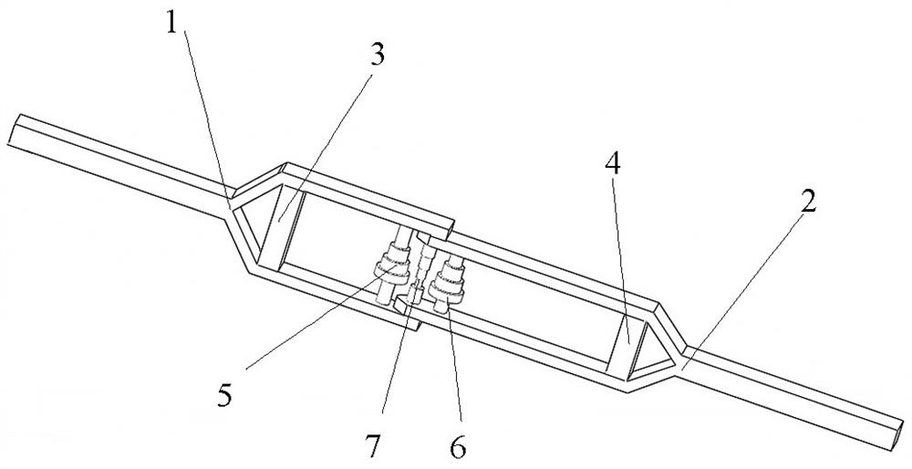
[0035] Such as figure 1 A steel bar bending device shown includes a main frame 1, a main auxiliary shaft 5 connected to the inside of the main frame 1, a sub-frame 2 connected to the end of the main frame 1, and a cross section connected to the intersection of the main frame 1 and the sub-frame 2. The bending mandrel 7 and the auxiliary auxiliary shaft 6 connected to the inside of the sub-frame 2; the bending mandrel 7 is rotationally connected to the main frame 1 and the sub-frame 2, the main auxiliary shaft 5 is rotationally connected to the main frame 1, and the auxiliary auxiliary shaft 6 is connected in rotation relative to the subframe 2; the diameter of the bending mandrel 7 is adapted to the design bending diameter of the steel bar 8, and the horizontal distance between the bending mandrel 7 and the main auxiliary shaft 5 and the auxiliary auxiliary shaft 6 is adapted to the bending diameter of the steel bar 8.

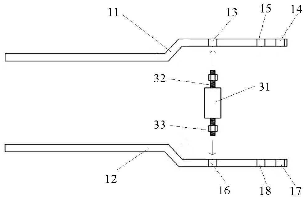
[0036] Such as figure 2 with image 3 Shown, main fra...


PUM

PropertyMeasurementUnit
radiusaaaaaaaaaa

Abstract

The invention discloses a construction method of a steel bar bending device, wherein the steel bar bending device comprises a main frame, a main auxiliary shaft connected to the inside of the main frame, a sub frame connected to the end of the main frame, and an intersection section connected to the main frame and the sub frame The bending mandrel shaft and the auxiliary auxiliary shaft connected to the inside of the sub-frame; during construction, the bending mandrel is rotationally connected to the main frame and the sub-frame, the main auxiliary shaft is rotationally connected to the main frame, and the auxiliary auxiliary shaft is rotationally connected to the sub-frame ; Through the setting of the bending mandrel, the main auxiliary shaft and the auxiliary auxiliary shaft, during construction, the steel bar will not slip or pop up when it is bent, and the bending mandrel, the main auxiliary shaft and the auxiliary auxiliary shaft are all rotatable connections, which is convenient for the reinforcement The uniform stress during bending achieves labor-saving effect; the setting of shafts with different diameters on the bending mandrel can adapt to the bending of steel bars with different diameters, and can be more suitable for site construction conditions; It can be set to adapt to different degrees of bending of steel bars during construction.

Description

technical field [0001] The invention relates to the technical construction field of steel bars, in particular to a construction method of a steel bar bending device. Background technique [0002] With the rapid development of the construction industry, steel engineering is an important part of the construction industry, especially reinforced concrete buildings. In steel bar engineering, there will be a phenomenon of on-site processing of steel bars, and the bending of steel bars is a common construction situation. The old-fashioned bending tools are inconvenient to operate, the bending center cannot be switched and rotated, and the steel bars are easy to slip out, resulting in unnecessary waste of manpower and potential safety hazards; there are also some electric steel bending tools or consoles, which are inconvenient Temporary use on site requires a certain amount of material and manpower for power consumption and transfer; therefore, it is necessary to provide a construc...

Claims


Application Information

Patent Timeline
Patent Type & Authority Patents(China)
IPC IPC(8): B21F1/00
CPCB21F1/004
Inventor 王云飞张静马威吕聃付佳男龙振业金龙郭磊
Owner BEIJING LIUJIAN CONSTR GRP
Why Eureka
Try Eureka