Clamping tool for drilling drive shaft
A driving shaft and clamping technology, which is applied in the direction of boring/drilling, drilling/drilling equipment, parts of boring machine/drilling machine, etc., can solve the problems of high failure rate, low drilling precision, drilling angle and drilling Hole position can not be accurately controlled to achieve the effect of ensuring drilling accuracy, avoiding excessive swing, and ensuring reliability
- Summary
- Abstract
- Description
- Claims
- Application Information
AI Technical Summary
Problems solved by technology
Method used
Image
Examples
Embodiment 1
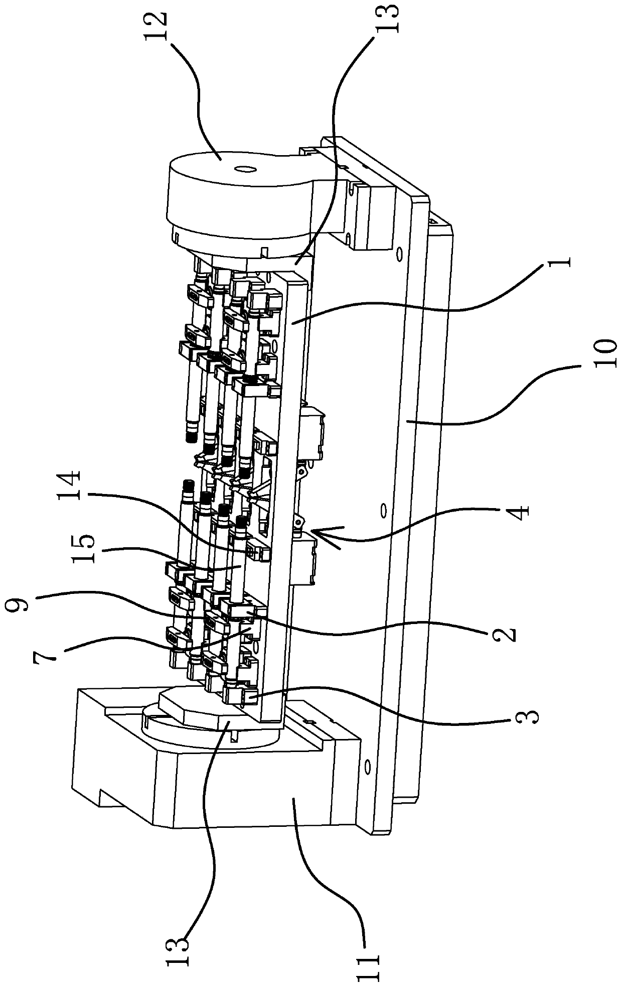
[0043] Such as figure 1 As shown, the clamping tool for drilling the drive shaft includes a rectangular base plate 10 and a turntable 11 and a tailstock 12 respectively fixed on the base plate 10. The turntable 11 and the tailstock 12 are arranged oppositely, and the turntable 11 is close to the base plate. One of the short sides of the bottom plate 10, and the tailstock 12 is close to the other short side of the bottom plate 10. The side opposite to the turntable 11 and the tailstock 12 is fixedly connected with a mounting base 13 with an L-shaped vertical section.
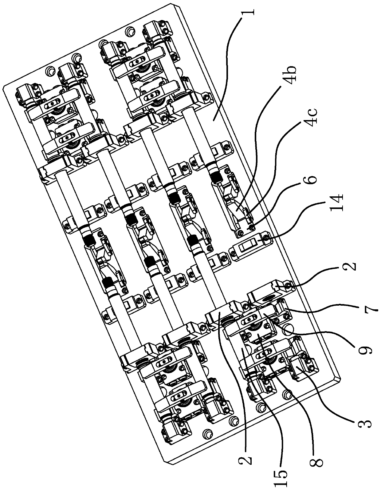
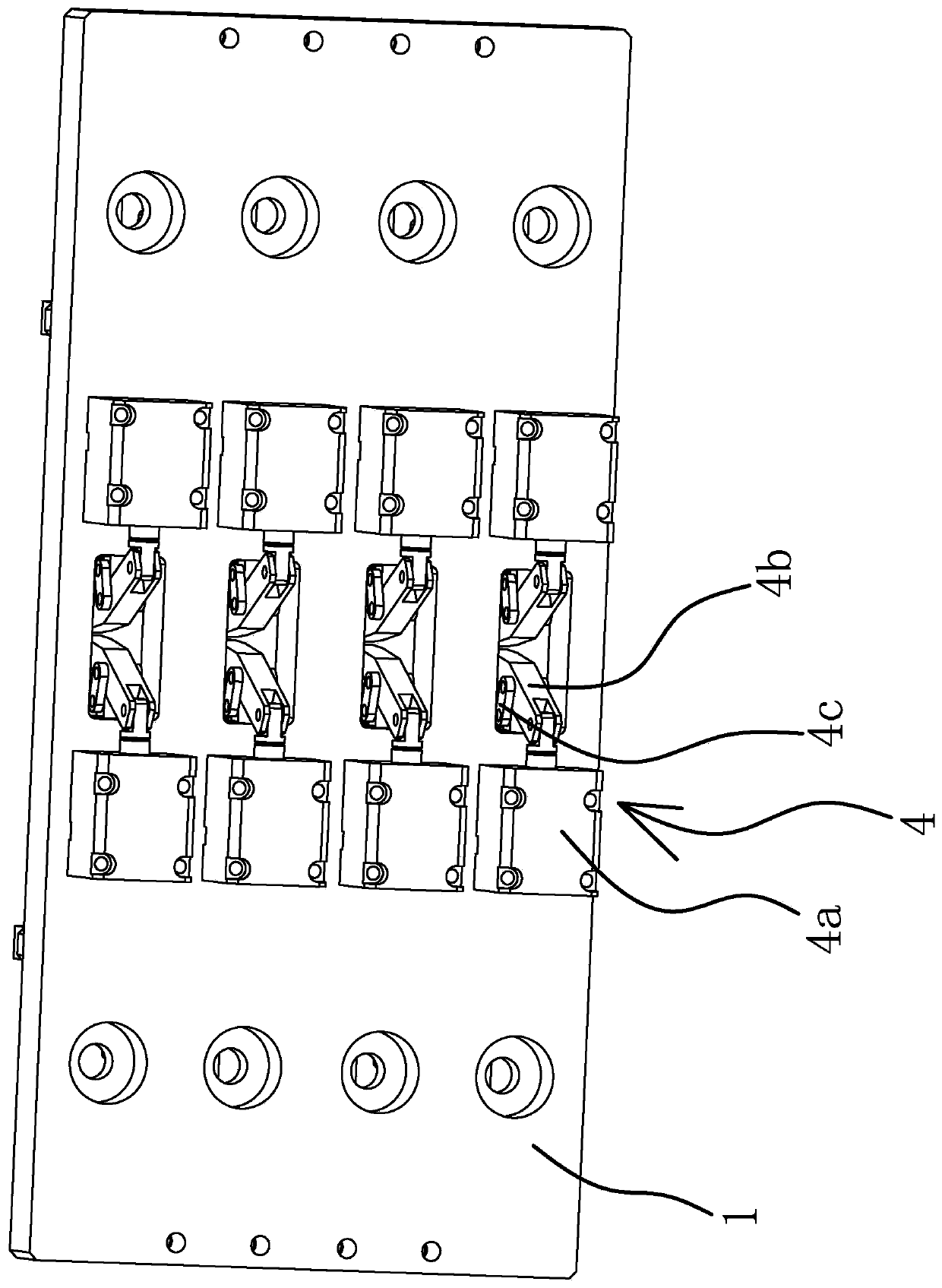
[0044] Such as figure 1 and figure 2 As shown, the upper surface of the substrate 1 is fixed with a support 2, and the side of the support 2 is provided with a positioning hole 2c1 for the drive shaft 15 to pass through. The positioning hole 2c1 is opened along the length direction of the bottom plate 10. The upper surface of the substrate 1 A block 3 is also fixed and a pressing mechanism 4 is provided. The ...
Embodiment 2
[0054] The structure and principle of this embodiment are basically the same as that of Embodiment 1, the difference is that in this embodiment, the elastic positioning assembly 5 includes a locking rod slidably arranged in the cavity 2a and a support spring sleeved on the locking rod , the embedded part 5a1 is fixedly connected to the upper end of the locking rod, and the locking rod always has a tendency to move upward under the elastic force of the support spring.
Embodiment 3
[0056] The structure and principle of this embodiment are basically the same as that of Embodiment 1, the difference is that in this embodiment, the pressing mechanism 4 includes a push cylinder fixed on the upper surface of the substrate 1, and the end of the piston rod of the push cylinder is fixedly connected with a The push plate can push the drive shaft 15 to move towards the block 3 when the piston rod of the cylinder is pushed out.
PUM
 Abstract
Description
Claims
Application Information
 - R&D
- Intellectual Property
- Life Sciences
- Materials
- Tech Scout
- Unparalleled Data Quality
- Higher Quality Content
- 60% Fewer Hallucinations
Browse by: Latest US Patents, China's latest patents, Technical Efficacy Thesaurus, Application Domain, Technology Topic, Popular Technical Reports.
© 2025 PatSnap. All rights reserved.Legal|Privacy policy|Modern Slavery Act Transparency Statement|Sitemap|About US| Contact US: help@patsnap.com


