Novel traction device used for pre-stressed steel strands

A technology of prestressed steel strand and traction device, which is applied in the directions of transportation and packaging, conveying filamentous materials, thin material processing, etc. It can solve the problems that the traction machine cannot be used conveniently, achieve reliable and efficient traction process, and improve contact The effect of saving area and labor intensity

Pending Publication Date: 2019-09-27
兰州斯凯特路桥预应力技术开发有限公司
View PDF0 Cites 4 Cited by
  • Summary
  • Abstract
  • Description
  • Claims
  • Application Information

AI Technical Summary

Problems solved by technology

[0003] The purpose of the present invention is to provide a new type of traction device for prestressed steel strands in order to solve the technical problem that the existing traction machine cannot be conveniently used in various working environments

Method used


Image

  • Novel traction device used for pre-stressed steel strands
  • Novel traction device used for pre-stressed steel strands
  • Novel traction device used for pre-stressed steel strands

Examples


Embodiment 1

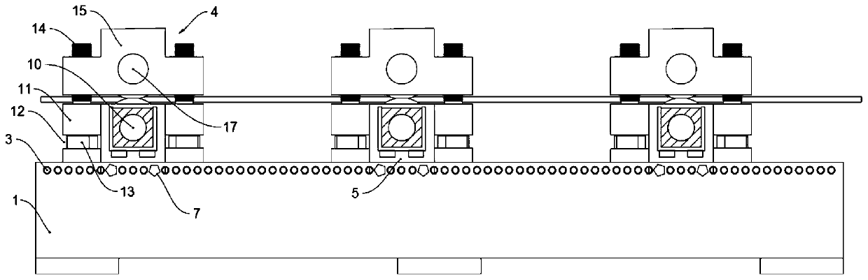
[0027] Such as Figure 1 to Figure 3 As shown, this embodiment provides a new type of traction device for prestressed steel strands, including a base 1, the upper surface of the base 1 is provided with a moving groove 2, and the front and rear ends of the moving groove 2 pass through the base 1 On the surface, a row of through holes 3 are horizontally provided on the left and right sides of the moving groove 2, and all the through holes 3 are evenly distributed in the horizontal direction and pass through the surface of the base 1. The upper surface of the base 1 is provided with a number of holes installed in the moving groove 2. The traction mechanism 4, the traction mechanism 4 includes the lower abutment 5 that can move in the moving groove 2, and the bottom of the left and right sides of the lower abutment 5 is provided with some positioning holes 6 that can coincide with the center line of the through hole 3, and the positioning holes 6 are inserted There is a fastener 7...

Embodiment 2

[0030] Such as Figure 1 to Figure 3 As shown, this embodiment is further optimized on the basis of embodiment 1, specifically:

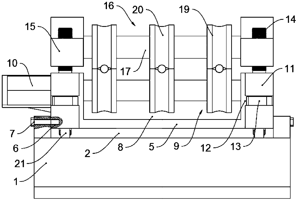
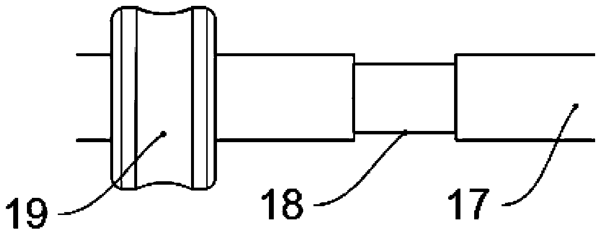
[0031] The upper traction group 16 and the lower traction group 9 have the same structure. The upper traction group 16 includes a rotating shaft 17 arranged in the middle of the upper base 15. The rotating shaft 17 is uniformly provided with a number of ring grooves 18 in the direction of the axis, and a traction wheel is clamped in the ring groove 18. 19.

[0032] In this embodiment, the design of multiple pairs of traction wheels 19 allows the entire traction device to simultaneously pull multiple steel strands, and the setting of the ring groove 18 can prevent the traction wheels 19 from moving left and right, ensuring that the traction wheels 19 are more stable and reliable during the traction process , effectively improving the practicability of the traction mechanism 4 .

Embodiment 3

[0034] Such as Figure 1 to Figure 3 As shown, this embodiment is further optimized on the basis of embodiment 1, specifically:

[0035]The central part of the surface of the traction wheel 19 is provided with a traction groove 20 in the circumferential direction.

[0036] In this embodiment, the traction groove 20 can increase the contact area between the surface of the traction wheel 19 and the surface of the steel strand, thereby increasing the friction force and making the traction process more reliable and efficient.


PUM


Abstract

The invention discloses a novel traction device used for pre-stressed steel strands and relates to the technical field of steel strand production and transportation equipment. Aiming at solving the technical problem that an existing traction machine fails to be applied to various working environments conveniently and fast, the novel traction device comprises a base, a moving groove is formed in the upper surface of the base, two rows of through holes are formed horizontally in the left and right side surfaces of the moving groove correspondingly, a plurality of traction mechanisms mounted inside the moving groove are arranged on the upper surface of the base, each traction mechanism comprises a lower base stand capable of moving in the moving groove, positioning holes are formed in the bottoms of the left and right side surfaces of each lower base stand correspondingly, fasteners arranged in the corresponding through holes are inserted into the positioning holes correspondingly, a working groove is formed in the upper surface of each lower base stand, two supporting stands are fixed to the front and rear side surfaces of each lower base stand correspondingly, an operating cavity is formed in the middle of each supporting stand, a bolt head is arranged in each operating cavity, a bolt rod penetrating out of the top surface of the corresponding supporting stand is fixed to the top surface of each bolt head, the upper portion of each bolt rod is connected with an upper base stand, and upper traction groups matched with corresponding lower traction groups are arranged in the middles of the upper base stands correspondingly.

Description

technical field [0001] The invention relates to the technical field of production and transportation equipment for steel strands, and more specifically relates to a novel traction device for prestressed steel strands. Background technique [0002] The steel strand is a steel product formed by twisting multiple steel wires. During the production of the steel strand, the steel strand needs to be transported from the silo to the bundling device. The tractor of the present technology uses upper and lower wheels to compress the steel strands, and the upper and lower wheels are tightly installed and cannot be easily moved, thus relying on frictional force to transport, which can reduce the work intensity of workers, but the steel strands that need to be transported are various , Different specifications lead to different diameters and weights, so the number of tractors used and the installation size of tractors are also different. The existing tractors must be reinstalled continuo...

Claims


Application Information

Patent Timeline
IPC IPC(8): B65H51/08
CPCB65H51/08B65H2701/36
Inventor 薛广浩牛东坡
Owner 兰州斯凯特路桥预应力技术开发有限公司
Why Eureka
Try Eureka