Hydraulic locking device for ram bop

A technology of ram blowout preventer and locking device, which is applied in wellbore/well components, earthwork drilling, sealing/isolation, etc., can solve the problems of easy wear and tear of the clutch sprocket, difficulty in unlocking, and large structural size, etc. Reliable action

Pending Publication Date: 2019-09-27
唐建华
View PDF3 Cites 4 Cited by
  • Summary
  • Abstract
  • Description
  • Claims
  • Application Information

AI Technical Summary

Problems solved by technology

[0006] The long wedge locking device locks reliably, but its structural size is large, and it is often difficult to unlock after locking, and its locking parts are easy to wear, which reduces its reliability
The structure of the screw tooth disc clutch type locking device is complex, limited by the mechanical principle, its locking position is discontinuous, the rigidity after locking is poor, and the clutch tooth disc has the problem of easy wear
The wedge-type locking device is usually located inside the oil cylinder, and its reliability is greatly affected by the hydraulic oil and other factors. The viscosity of the hydraulic oil, the degree of pollution, the ambient temperature, and the surface roughness of the parts will all affect it. It is prone to problems such as inability to lock, and difficulty in unlocking after locking. This type of locking device generally does not have an external display mechanism, and it is difficult for the operator to understand its working status.

Method used


Image

  • Hydraulic locking device for ram bop
  • Hydraulic locking device for ram bop
  • Hydraulic locking device for ram bop

Examples


Embodiment Construction

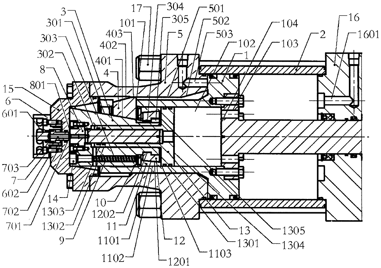
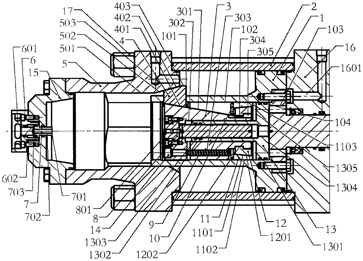
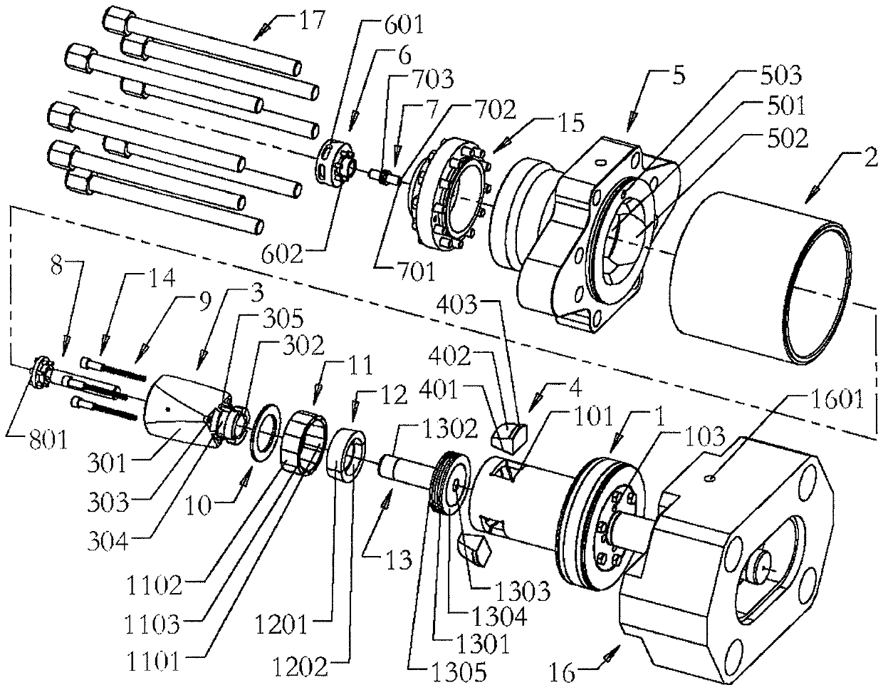
[0048] The invention will be described in detail below with reference to the accompanying drawings.

[0049] The locking device is composed of a main locking mechanism and a synchronous locking mechanism. The main locking mechanism includes a piston assembly 1, a wedge sleeve 3, a wedge block 4, and a liquid lock cylinder 5. The wedge block 4 is assembled on the piston assembly 1. In the front square hole 101, the lower inclined surface 401 of the wedge block 4 is in contact with the inclined surface 301 of the wedge sleeve 3. The wedge sleeve 3 and the wedge block 4 adopt a larger wedge angle design, and the wedge block 4 follows the axial direction of the piston 1. Movement, so that the top of the wedge 4 moves back and forth in the slideway of the liquid lock cylinder 5. At the front end of the main locking mechanism, a synchronous locking mechanism composed of a cone ring 12 preloaded by a spring 9 and a cone disc 11 is provided. corner design. The locking action of the ...


PUM


Abstract

The invention discloses a hydraulic locking device for a ram bop. The hydraulic locking device for the ram bop is characterized in that the locking device consists of a main locking mechanism and a synchronous locking mechanism, the main locking mechanism comprises a piston component, a wedge sleeve, a wedge block and a liquid lock cylinder, the wedge block is mounted within a square hole in front of piston component, the lower bevel of the wedge block attaches to the bevel of the wedge sleeve, the wedge block moves axially with a piston, making the top of the wedge block move back and forth in the slide of the liquid lock cylinder, the front end of the main locking mechanism is provided with a synchronous locking mechanism composed of a spring pre-tightening cone ring and a cone disk, and a display mechanism composed of a differential piston, a protective cap and a cylinder head is arranged at the end of the liquid locking cylinder, so that the working state of the mechanism can be observed from the outside. According to the hydraulic locking device, the structure is compact, the design is reasonable, the locking and the unlocking are not affected by the state of hydraulic oil and other factors. When the main locking mechanism is locked, the synchronous locking mechanism is locked synchronously to make the locking more reliable. Locking force is provided by a locking plunger to reduce component wear and unlocking force is provided by an unlocking piston for easier unlocking.

Description

technical field [0001] The invention relates to a petroleum machinery, in particular to a hydraulic locking device of a ram blowout preventer. Background technique [0002] At present, the known technologies include, for example: Chinese invention patent CN108756803A discloses a hydraulic double ram BOP, including: an integrated hydraulic cylinder, a semi-closed ram, a fully-closed ram, a closing rod, an opening rod, an inlet Oil flange and blind flange; semi-sealed ram and full-sealed ram are both flat and set inside the blowout preventer body; semi-sealed ram and fully-sealed ram are connected with integrated hydraulic cylinder; closing rod and the opening lever are fixed on the blowout preventer body and communicate with the oil inlet flange respectively; the closing lever and the opening lever are respectively matched with the blowout preventer cover, and the blowout preventer cover is connected with the blowout preventer body cover; the blind flange Connect with the oi...

Claims


Application Information

Patent Timeline
Patent Type & Authority Applications(China)
IPC IPC(8): E21B33/06
CPCE21B33/061
Inventor 唐建华
Owner 唐建华
Why Eureka
Try Eureka