
Hierarchical arrangement system of water feeding pump of thermal power plant

A technology for feed water pumps and thermal power plants, which is applied in the field of graded arrangement system of feed water pumps in thermal power plants. It can solve problems such as high energy consumption, increased operating losses of units, and complicated bypass design of high-pressure heaters. It achieves flexible operation, increased efficiency, and reduced The effect of quality requirements

Inactive Publication Date: 2019-09-27
XI AN JIAOTONG UNIV
View PDF3 Cites 1 Cited by
  • Summary
  • Abstract
  • Description
  • Claims
  • Application Information

AI Technical Summary

Problems solved by technology

[0002] Since the power plant's main feed water pump consumes a lot of energy, which accounts for a high part of the power consumption of the plant, optimizing the feed water pump can reduce the energy consumption of the auxiliary equipment of the unit; and due to the high pressure of the main feed water, higher requirements are put forward for the quality of the high-pressure heater , which increases the investment cost of the high-pressure heater, and is not conducive to the stable operation of the high-pressure heater; because the main feed water pressure is high, the bypass design of the high-pressure heater alone is complicated. At present, the high-pressure heater in the power plant uses the same bypass. When it is necessary to shut down, all high-speed generators need to be shut down, which increases the operating loss of the unit and does not take advantage of the flexible operation of the unit

Method used


Image

  • Hierarchical arrangement system of water feeding pump of thermal power plant

Examples


Embodiment Construction

[0012] The present invention will be described in further detail below in conjunction with the accompanying drawings and specific embodiments.

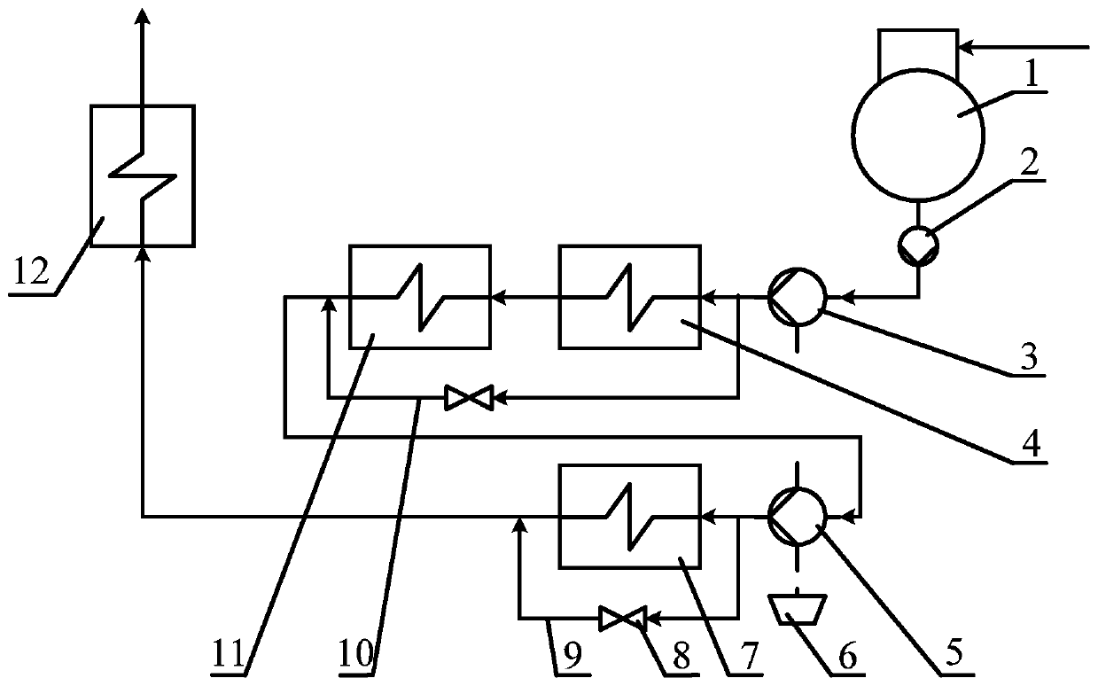
[0013] Such as figure 1 As shown, the present embodiment is a thermal power plant feedwater pump hierarchical arrangement system, including two-stage feedwater pumps and two-stage high-pressure heater bypasses; the two-stage feedwater pumps include a first-stage feedwater pump 3 and a second-stage feedwater pump 5 , the first-stage feedwater pump 3 is arranged between the feedwater pump front pump 2 and 1# high-pressure heater 4, and the second-stage feedwater pump 5 is arranged between 2# high-pressure heater 11 and 3# high-pressure heater 7; The two-stage high-pressure heater bypass includes a first-stage high-pressure heater bypass 10 and a second-stage high-pressure heater bypass 9, and the pipeline of the first-stage high-pressure heater bypass 10 is arranged in the first-stage feed water pump 3 Between the second-stage feed wat...


PUM


Abstract

The invention provides a hierarchical arrangement system of a water feeding pump of a thermal power plant. The system involves two stages of water feeding pumps and two stages of high-pressure heater bypasses; a first-stage water feeding pump is arranged between a water feeding pump front-end pump and a first high-pressure heater, and a second-stage water feeding pump is arranged between a penultimate-stage high-pressure heater and a last-stage high-pressure heater; a pipeline of a first-stage high-pressure heater bypass is arranged between the first-stage water feeding pump and the second-stage water feeding pump and is in parallel connection with a high-pressure heater between the first-stage water feeding pump and the second-stage water feeding pump, and a pipeline of a second-stage high-pressure heater bypass is arranged behind the second-stage water feeding pump and is in parallel connection with the last-stage high-pressure heater; and bypass valves are arranged on the pipelines of the first-stage high-pressure heater bypass and the second-stage high-pressure heater bypass. According to the system, the main water supply of the power plant is boosted through the two stages of the water feeding pumps, so that the water supply pressure of the first-stage water feeding pump is reduced, the material requirement of the high-pressure heaters is reduced, and meanwhile, a unit is enabled to operate efficiently and flexibly, and the efficiency of the unit is increased.

Description

technical field [0001] The invention relates to the technical field of energy and power, in particular to a hierarchical arrangement system for feedwater pumps in thermal power plants. Background technique [0002] Since the power plant's main feed water pump consumes a lot of energy, which accounts for a high part of the power consumption of the plant, optimizing the feed water pump can reduce the energy consumption of the auxiliary equipment of the unit; and due to the high pressure of the main feed water, higher requirements are put forward for the quality of the high-pressure heater , which increases the investment cost of the high-pressure heater, and is not conducive to the stable operation of the high-pressure heater; because the main feed water pressure is high, the bypass design of the high-pressure heater alone is complicated. At present, the high-pressure heater in the power plant uses the same bypass. When it is necessary to shut down, all high-speed generators n...

Claims


Application Information

Patent Timeline
Patent Type & Authority Applications(China)
IPC IPC(8): F22D11/06F22D1/50F22D1/00
CPCF22D1/003F22D1/50F22D11/06
Inventor 张顺奇刘枫刘继平严俊杰
Owner XI AN JIAOTONG UNIV
Learn More