Radio frequency coil device for magnetic resonance head and neck imaging

A technology of radio frequency coil and head coil, which is applied in magnetic resonance measurement, measurement device, measurement of magnetic variables, etc., can solve the problems of complex structure of head and neck imaging coil, inconvenient use, poor imaging effect, etc., and achieves convenient wearing and improved effect. , the effect of optimizing the user experience

Pending Publication Date: 2019-09-27
SUZHOU MEDCOIL HEALTHCARE
View PDF5 Cites 4 Cited by
  • Summary
  • Abstract
  • Description
  • Claims
  • Application Information

AI Technical Summary

Problems solved by technology

[0005] However, the existing head and neck imaging coils have complex structures and unreasonable designs, which lead to inconvenient use and poor imaging effects.

Method used


Image

  • Radio frequency coil device for magnetic resonance head and neck imaging
  • Radio frequency coil device for magnetic resonance head and neck imaging
  • Radio frequency coil device for magnetic resonance head and neck imaging

Examples


Embodiment 1

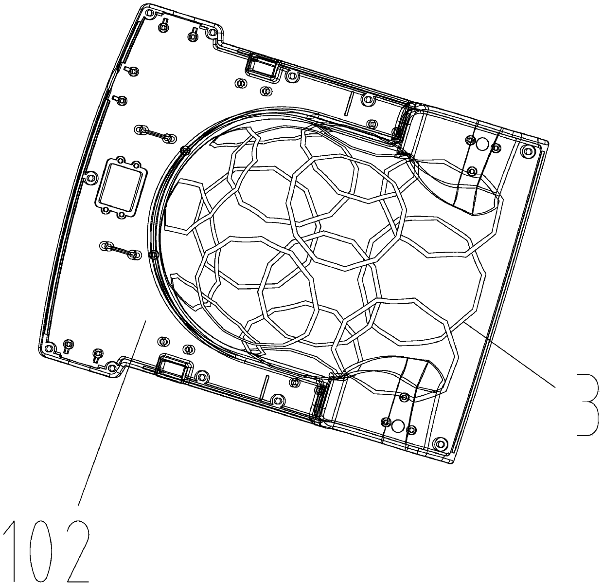
[0039] Figure 1 to Figure 11 It shows a preferred embodiment of the radio frequency coil device for magnetic resonance head and neck imaging of the present application. Like some traditional radio frequency coil devices, the device also includes a coil support shell and is fixed in the shell wall of the coil support shell. A plurality of coil units 3, each coil unit 3 is an annular copper coil.

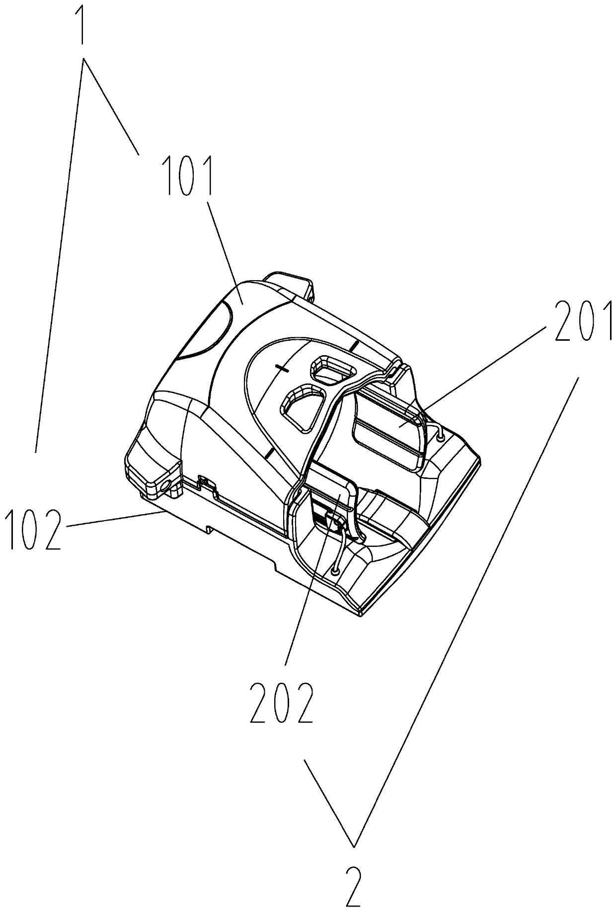
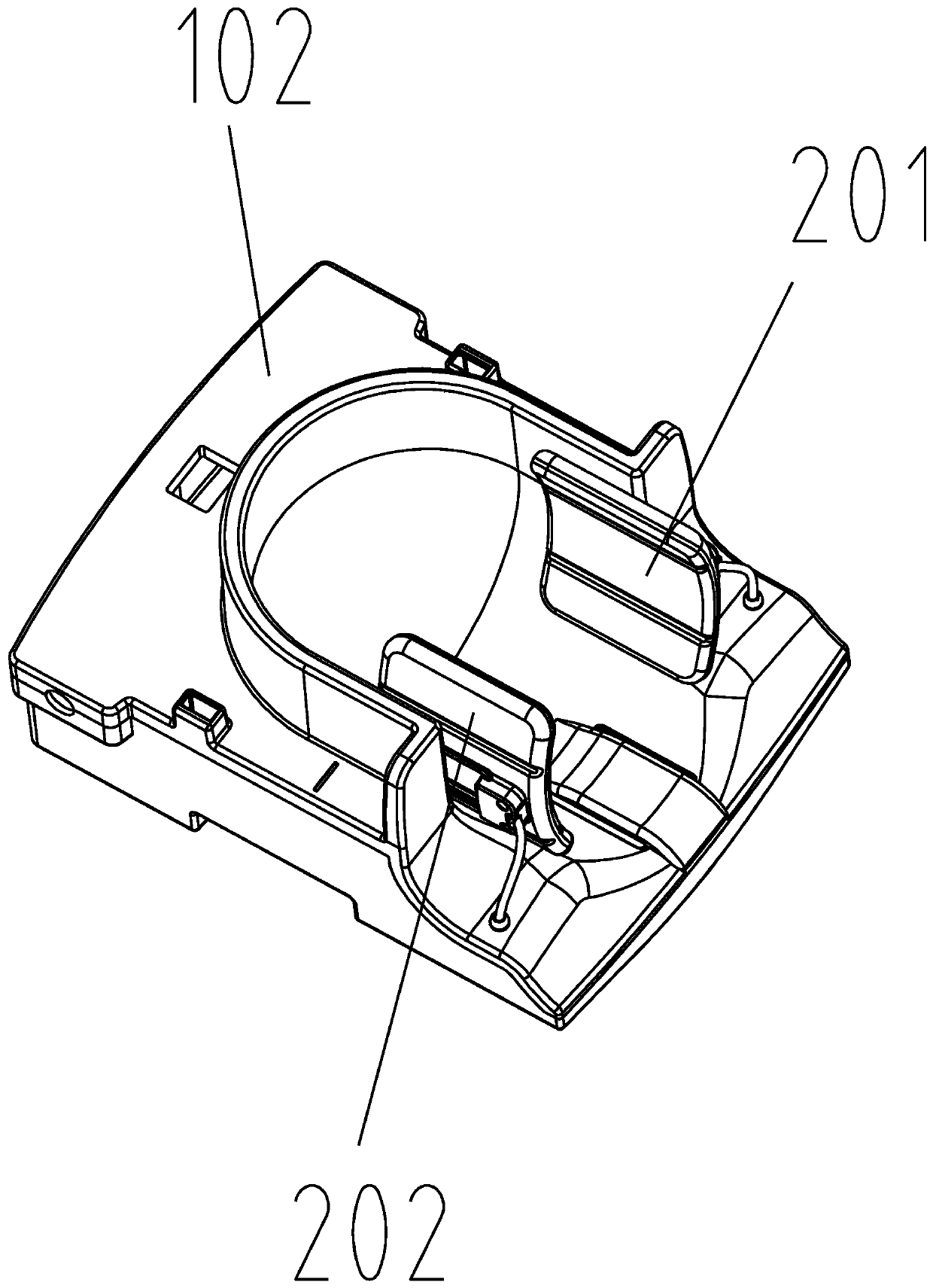
[0040] The key improvement of this embodiment is that the above-mentioned coil support case is composed of a head coil support case 1 and a neck coil support case 2, wherein the head coil support case 1 is formed with a head for the examinee’s head to extend into. The neck coil supporting shell 2 has a neck housing cavity for the examinee's neck to extend into.

[0041]The above-mentioned head coil supporting shell 1 is composed of (during imaging inspection) the front half shell 101 located on the front side of the examinee's head and the rear half shell 102 on the back side of the...

Embodiment 2

[0056] Figure 12 and Figure 13 Another preferred embodiment of the radio frequency coil device for magnetic resonance head and neck imaging of the present application is shown. The structure of the radio frequency coil device is basically the same as that of the first embodiment, and a total of 32 coil units are configured. The difference is: in this embodiment, 8 coil units 3 are fixedly arranged in the shell wall of the front half shell 101, 18 coil units 3 are fixedly set in the shell wall of the rear half shell 102, the left half shell 201 and the right half shell Three coil units 3 are respectively fixedly arranged in the shell wall of 202 .

[0057] Refer again Figure 12 As shown, the 18 coil units 3 in the shell wall of the rear half shell 102 are sequentially divided into the eighth coil group h, the ninth coil group i, the tenth coil group j and the eleventh coil along the direction of the examinee's head and feet. Group k and the twelfth coil group l have a tot...


PUM


Abstract

The invention discloses a radio frequency coil device for magnetic resonance head and neck imaging. The radio frequency coil device comprises a coil supporting shell and a plurality of annular coil units fixed onto the shell wall of the coil supporting shell; the coil supporting shell is composed of a head coil supporting shell and a neck coil supporting shell, a head containing cavity being defined in the head coil supporting shell, a neck containing cavity being defined in the neck coil supporting shell; the head coil supporting shell is composed of a front half shell located at the front side of the head of a person to be examined and a rear half shell located at the back side of the head of the person to be examined; the neck coil supporting shell is composed of a left half shell located at the left side of the neck of the person to be examined and a right half shell located at the right side of the neck of the person to be examined; and a plurality of coil elements are fixedly arranged in the shell walls of the front half shell, the rear half shell, the left half shell and the right half shell. The various coil units in the device are reasonable in arrangement and dense in distribution, and therefore, the advantage of partial overlapping decoupling is utilized to the greatest extent, and the effect of the head and neck imaging is improved.

Description

technical field [0001] The present application relates to a radio frequency coil device for magnetic resonance head and neck imaging. Background technique [0002] Magnetic resonance imaging technology has become an important means of clinical diagnosis in modern medicine. It has the advantages of high tissue density contrast, slice imaging in any orientation, and no ionizing radiation, and it is more and more widely used. [0003] The RF receiving coil is an important part of the imaging system. There are many types due to the different scanning parts. It is at the forefront of the receiving chain and plays a decisive role in the imaging quality, directly affecting the quality of the imaging. At the same time, compared with other components in the magnetic resonance system, the radio frequency coil is easier to develop and optimize, so it has always been a hot spot in the field of magnetic resonance imaging. [0004] The number and arrangement of coil units in the radio fr...

Claims


Application Information

Patent Timeline
Patent Type & Authority Applications(China)
IPC IPC(8): G01R33/34G01R33/36
CPCG01R33/34046G01R33/3642
Inventor 杨旗尚海方朱华彬
Owner SUZHOU MEDCOIL HEALTHCARE
Why Eureka
Try Eureka