Map construction method and device and terminal equipment

A map construction and sub-map technology, which is applied in the direction of measuring devices, 3D modeling, image data processing, etc., can solve problems such as errors, cumulative errors, and poor mapping effects

Active Publication Date: 2019-09-27
SHENZHEN UNIV
View PDF4 Cites 5 Cited by
  • Summary
  • Abstract
  • Description
  • Claims
  • Application Information

AI Technical Summary

Problems solved by technology

[0004] The main purpose of the present invention is to propose a map construction method, device and terminal equipment to solve the problem that the initial value optimization in the prior art produces errors during the map construction process and accumulates errors, making the map construction effect poor

Method used


Image

  • Map construction method and device and terminal equipment
  • Map construction method and device and terminal equipment
  • Map construction method and device and terminal equipment

Examples


Embodiment 1

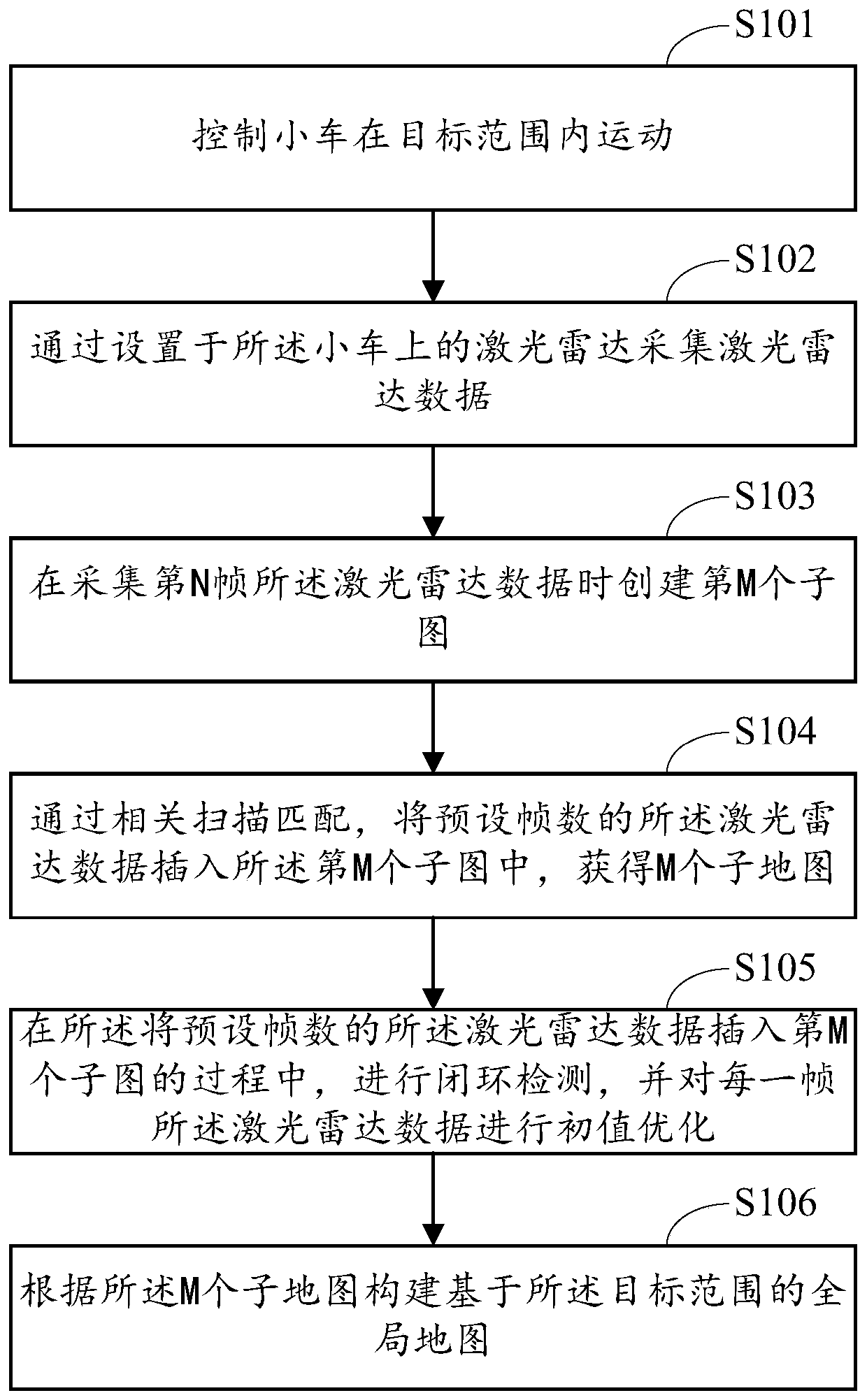
[0066] Such as figure 1 As shown, Embodiment 1 of the present invention provides a method for constructing a map, including:

[0067] S101. Control the car to move within the target range.

[0068] In the above step S101, the target range represents the range where map construction needs to be performed.

[0069] In a specific application, the trolley can be an AGV (Automated Guided Vehicle), and the AGV is equipped with an automatic guidance device such as electromagnetic or optical, and travels along a prescribed guidance path.

[0070] In the embodiment of the present invention, the guidance path can be planned within the target range, so that the car can acquire information in the target range that can be used for map construction during driving.

[0071] S102. Collect laser radar data through the laser radar installed on the trolley.

[0072] In the above step S102, the lidar can directly acquire data such as distance, angle, reflection intensity, and speed from the ta...

Embodiment 2

[0090] The embodiment of the present invention explains the implementation of sub-step S1051 of step S105 in the first embodiment above, and illustrates the detailed process of initial value optimization therein.

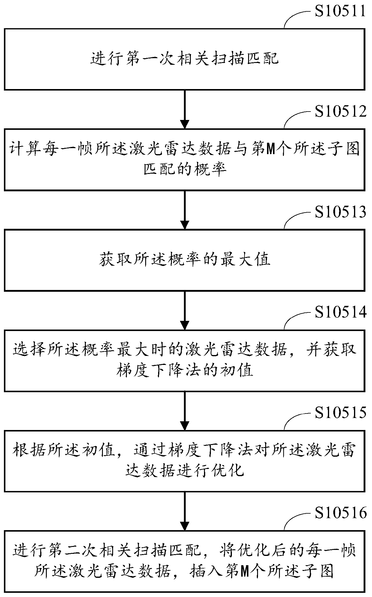
[0091] Such as image 3 As shown, in the embodiment of the present invention, step S1051 may include the following implementation steps:

[0092] S10511. Perform the first correlation scan matching.

[0093] In the above step S10511, after the first correlation scan matching, the result will be processed, and the processed result will be used as the input of the second correlation scan matching.

[0094] S10512. Calculate the probability that the lidar data of each frame matches the Mth sub-image, the formula is:

[0095]

[0096] where x i Indicates the pose of the car at the current moment, and the pose of the car at the previous moment is x i-1 , z represents any frame of lidar data, j represents the preset number of frames, m represents the world model, a...

Embodiment 3

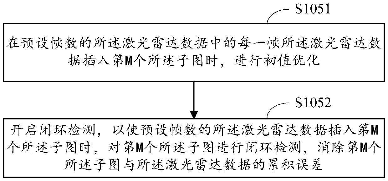
[0112] In this embodiment of the present invention, an implementation manner of sub-step S1052 of step S105 in the first embodiment is explained, and a detailed process of closed-loop detection therein is described.

[0113] Such as Figure 4 As shown, in the embodiment of the present invention, step S1052 may include the following implementation steps:

[0114] S10521. Set the detection period.

[0115] S10522. At each interval of the detection cycle, search for a key frame in the lidar data of the preset number of frames, and perform closed-loop detection through the lidar data of the key frame, and eliminate the Mth sub-image and the difference according to the closed-loop detection result The cumulative error of the lidar data.

[0116] Wherein, the lidar data whose detection period is shorter than the preset number of frames is inserted into the Mth subimage, and the lidar data of the preset number of frames is inserted into the period of the M+1th subimage.

[0117] I...


PUM


Abstract

The invention is applicable to the technical field of mobile robot navigation, and provides a map construction method and device and terminal equipment, and the method comprises the steps: controlling a trolley to move in a target range; collecting laser radar data through a laser radar arranged on the trolley; when the Nth frame of laser radar data is collected, creating an Mth subgraph, wherein N and M are positive integers, and the initial values of N and M are both 1; inserting laser radar data with a preset frame number into the Mth sub-image through related scanning matching to obtain M sub-maps; in the process of inserting the laser radar data with the preset frame number into the Mth subgraph, carrying out closed-loop detection, and carrying out initial value optimization on each frame of laser radar data; and constructing a global map based on the target range according to the M sub-maps. According to the invention, the matching error between each frame of laser radar data and the sub-map and the matching error accumulated by the laser radar data and the sub-map in each sub-map can be reduced, so that the finally constructed global map is accurate and reliable.

Description

technical field [0001] The invention relates to the technical field of mobile robot navigation, in particular to a map construction method, device and terminal equipment. Background technique [0002] When solving the model parameters of the machine learning algorithm, that is, obtaining the minimized loss function and model parameter values, the gradient descent method and iterative calculation method are the most commonly used methods. For example, when constructing a map for a robot, the initial value optimization is usually used to reduce the error of map construction. Among them, the iterative and gradient descent methods are sensitive to the initial value, and the selection of the initial value has a great impact on the final scan matching result. It is better The initial value of can make scan matching easy to converge and get better results, and the poor initial value is easy to fall into local minimum and non-convergence. Therefore, in order to provide a better ini...

Claims


Application Information

Patent Timeline
Patent Type & Authority Applications(China)
IPC IPC(8): G06T17/05G01S17/06G01S17/89
CPCG06T17/05G01S17/06G01S17/89Y02T10/40
Inventor 蒙山蔡光辉
Owner SHENZHEN UNIV
Why Eureka
Try Eureka