Method of improving insulation performance of chip resistor unit

A technology of insulation performance and resistance, applied in the direction of I-shaped/sine-shaped resistance elements, etc., can solve the problems of shortening the creepage distance, affecting the insulation performance of resistance units, and failing to meet the high-voltage requirements of the rainy environment, so as to achieve simplified isolation. way, improve the overall insulation performance, and meet the effect of high voltage resistance requirements

Active Publication Date: 2019-09-27
SHIDAI ELECTRIC FACTORY ZHUZHOU ELECTRIC LOCOMOTIVES INST MIN OF RAILWAYS
View PDF7 Cites 5 Cited by
  • Summary
  • Abstract
  • Description
  • Claims
  • Application Information

AI Technical Summary

Problems solved by technology

[0008] The purpose of the present invention is to solve the problem of shortening the creepage distance in the rainy environment by using a single porcelain piece for the insulation isolation between the porcelain piece and the resistance band or the resistance piece in the existing chip resistor, which affects the resistance unit in the rainy environment. The insulation performance cannot meet the high-voltage requirements in the rainy environment. A new type of isolation insul

Method used


Image

  • Method of improving insulation performance of chip resistor unit
  • Method of improving insulation performance of chip resistor unit
  • Method of improving insulation performance of chip resistor unit

Examples


Embodiment 1

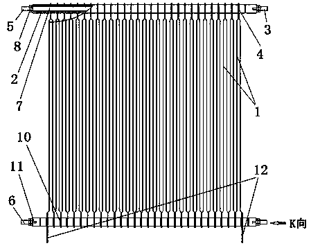
[0034] by attaching Figure 2-5 It can be seen that the present invention relates to a resistance unit with a combination structure of resistance bands, comprising a support rod 3, a resistance band 1 and a whole insulating tube 2, and the resistance unit is formed by combining the support bar 3, the resistance band 1 and the whole insulating tube 2. In the unit, the isolation and positioning of the two ends 4 of the upper and lower detours of the resistance band 1 are performed through the entire insulating tube.

[0035] The support rod 3 is a cylindrical metal rod commonly called a tie rod, and there are two support rods 3, which are respectively the first support rod 5 and the second support rod 6; the first support rod 5 and the second support rod The support rods 6 are respectively located at the upper and lower ends 4 of the resistance band 1, and pass through the central hole 7 on the entire insulating tube 2, and the two ends of the entire insulating tube 2 protrude o...

Embodiment 2

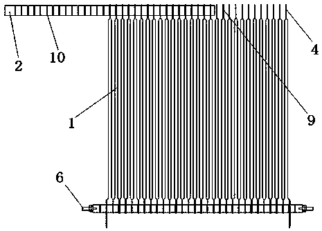
[0042] The principle of embodiment two is the same as embodiment one, but slightly different in structure, as attached Figure 6-7 As shown, the resistance unit of the combined structure of the resistance band comprises a support rod 203, a resistance band 201, a whole insulating tube 202 and a conductor 213, and the resistance unit is formed by combining the support bar 203, the resistance band 201 and the whole insulating tube 202; The isolation and positioning of the two ends of the belt 202 are carried out through the entire insulating tube 202 .

[0043] The support rod 203 is a cylindrical metal rod commonly called a tie rod, and there are two support rods 203, which are respectively the first support rod and the second support rod; the first support rod and the second support rod They are respectively located at the two ends of the resistance band 201, and pass through the center hole on the entire insulating tube 202, and the two ends protrude out of the entire insulat...


PUM


Abstract

The invention discloses a method of improving the insulation performance of a chip resistor unit. Resistor strips or resistor chips are arranged together, adjacent resistor strips or resistor chips are isolated by an insulation material, an integral insulation tube is adopted to isolate the adjacent resistor strips or resistor chips, and through the integral insulation tube, isolation, insulation and positioning are carried out between adjacent resistor strips or resistor chips. Clamping grooves are opened in the integral insulation tube, all resistor strips or resistor chips are clamped in the clamping grooves in the integral insulation tube, and through the clamping grooves, isolation, insulation and positioning are formed among the resistor strips or resistor chips. The resistor strips or resistor chips are clamped through the integral insulation tube. The resistor strips or resistor chips can be effectively positioned, insulation and isolation between the resistor strips or resistor chips can be effectively realized, the creepage distance of the resistor strips or resistor chips is greatly increased, problems such as moisture to affect the insulation performance do not happen, and the insulation performance of the resistor unit is improved.

Description

technical field [0001] The present invention relates to a structure of a resistor and an insulation method thereof, in particular to a method for improving the insulation performance between resistance bands or resistance plates of a chip resistor, which improves the resistance band or resistance of a chip resistor The method for the insulation performance between sheets can improve the insulation performance between resistance bands or resistance sheets in a resistor unit, and increase the creepage distance and withstand voltage value of the resistance bands or resistance sheets; it belongs to the technical field of chip resistor manufacturing. Background technique [0002] Chip resistor is a very widely used resistor. For example, on the current electric locomotive, in order to make the high-speed train or high-speed rail brake at a smooth speed, it is necessary to convert the kinetic energy and potential energy through the braking resistor. The generated electric energy i...

Claims


Application Information

Patent Timeline
IPC IPC(8): H01C3/10H01C3/12
CPCH01C3/10H01C3/12
Inventor 张利生肖宁吴志云朱继贤
Owner SHIDAI ELECTRIC FACTORY ZHUZHOU ELECTRIC LOCOMOTIVES INST MIN OF RAILWAYS
Why Eureka
Try Eureka