
Inverter device and electric vehicle

An inverter and circuit technology, applied in the field of inverter devices and electric vehicles, can solve the problems of increasing output voltage error, increasing inverter output error, reducing the number of PWM pulses, etc., so as to reduce the output voltage error. Effect

Active Publication Date: 2019-09-27
HITACHI ASTEMO LTD
View PDF5 Cites 2 Cited by
  • Summary
  • Abstract
  • Description
  • Claims
  • Application Information

AI Technical Summary

Problems solved by technology

Therefore, when the inverter output frequency is high, the number of PWM pulses decreases, and the output error of the inverter increases.
In addition, in the overmodulation mode in which the output voltage command of the inverter exceeds the maximum output level (sine wave) of the inverter, the output voltage error will increase

Method used


Image

  • Inverter device and electric vehicle
  • Inverter device and electric vehicle
  • Inverter device and electric vehicle

Examples


Embodiment Construction

[0021] The present invention is an inverter device that drives a semiconductor switching element by PWM control. When performing trapezoidal wave modulation using a trapezoidal wave in an overmodulation region where the modulation rate is equal to or higher than a predetermined value, the phase of the trapezoidal wave is changed based on the phase of the trapezoidal wave. The pulse width of the PWM pulse is varied at the predetermined timing above to provide a high-output inverter device. Hereinafter, one embodiment of the present invention will be described using the drawings.

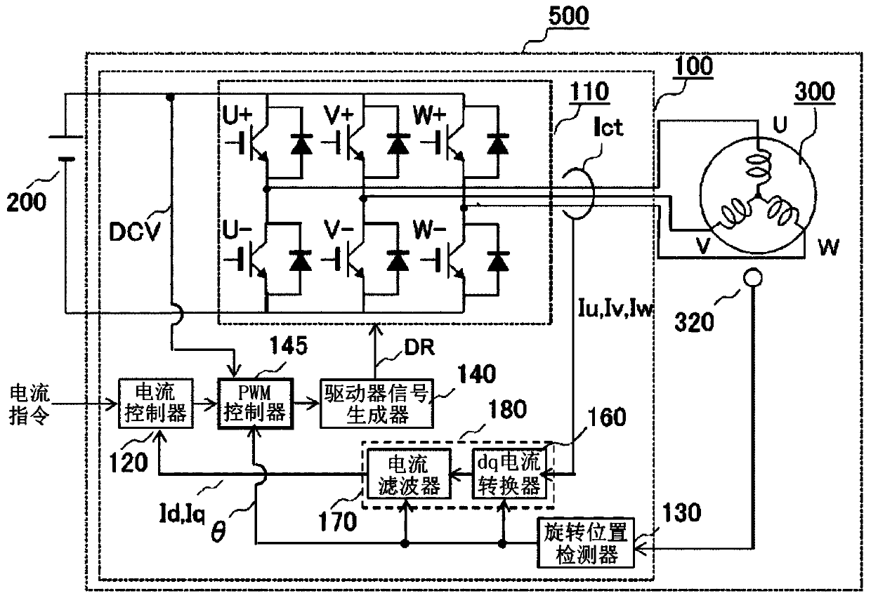
[0022] figure 1 It is a block diagram showing the configuration of a motor device 500 including the inverter device 100 of the present invention. The motor device 500 has a motor 300 and an inverter device 100 . The motor device 500 is suitable for detecting an installation position error of the rotational position sensor of the motor 300 and correcting it when the motor is driven to efficiently dri...


PUM


Abstract

The present invention addresses the problem of reducing output voltage errors of an inverter circuit and stably controlling a motor up to high-speed rotation. An inverter device (100) includes: a PWM controller (145) for generating a PWM pulse for converting a DC voltage into an AC voltage on the basis of a motor output demand; and an inverter circuit (110) for converting a DC voltage into an AC voltage according to the PWM pulse generated by the PWM controller (145), and driving a motor (300). The PWM controller (145) changes, when performing trapezoidal wave modulation using a trapezoidal wave in an overmodulation region, the pulse width of the PWM pulse at a predetermined timing at the upper side of the trapezoidal wave.

Description

technical field [0001] The present invention relates to an inverter device and an electric vehicle. Background technique [0002] An asynchronous PWM method in which PWM control is performed with a carrier frequency constant for a variable output frequency of the inverter is often employed in an inverter drive device that performs PWM (pulse width modulation) control to drive a motor. Therefore, when the inverter output frequency is high, the number of PWM pulses decreases, and the output error of the inverter increases. In addition, in the overmodulation mode in which the output voltage command of the inverter exceeds the maximum output level (sine wave) of the inverter, the output voltage error increases. [0003] Patent Document 1 describes a technique for minimizing an output voltage error by generating PWM pulses in an angular interval linearly approximated around a zero-crossing point of an output voltage of an inverter. [0004] prior art literature [0005] patent...

Claims


Application Information

Patent Timeline
Patent Type & Authority Applications(China)
IPC IPC(8): H02M7/48H02P27/08
CPCB60L15/08B60L2210/40B62D5/046B60L50/61H02M7/53875H02M7/5395H02P27/08Y02T10/62Y02T10/64Y02T10/70Y02T10/72B60K6/22B60L2210/14B60Y2200/91B60Y2200/92B60Y2400/61B62D5/04B60L50/60H02M7/53871
Inventor 安岛俊幸矶部纯希高冈碧芦田明广田村浩志
Owner HITACHI ASTEMO LTD
Learn More