
A circuit and method suitable for parallel current sharing of high-power switching power supplies

A high-power switching and paralleling technology, applied in the output power conversion device, electrical components and other directions, can solve the problems of limited current sharing adjustment range, low current sharing accuracy, etc., to achieve simple and convenient lines, ensure normal and reliable operation, The effect of improving bandwidth and gain

Active Publication Date: 2019-09-20
TIANSHUI 749 ELECTRONICS
View PDF3 Cites 0 Cited by
  • Summary
  • Abstract
  • Description
  • Claims
  • Application Information

AI Technical Summary

Problems solved by technology

[0005] In order to solve the above-mentioned phenomenon of low current sharing accuracy and limited current sharing adjustment range, the present invention provides a circuit suitable for parallel connection of high-power switching power supplies

Method used


Image

  • A circuit and method suitable for parallel current sharing of high-power switching power supplies
  • A circuit and method suitable for parallel current sharing of high-power switching power supplies
  • A circuit and method suitable for parallel current sharing of high-power switching power supplies

Examples


Embodiment 1

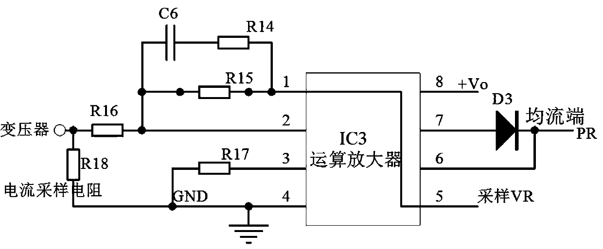
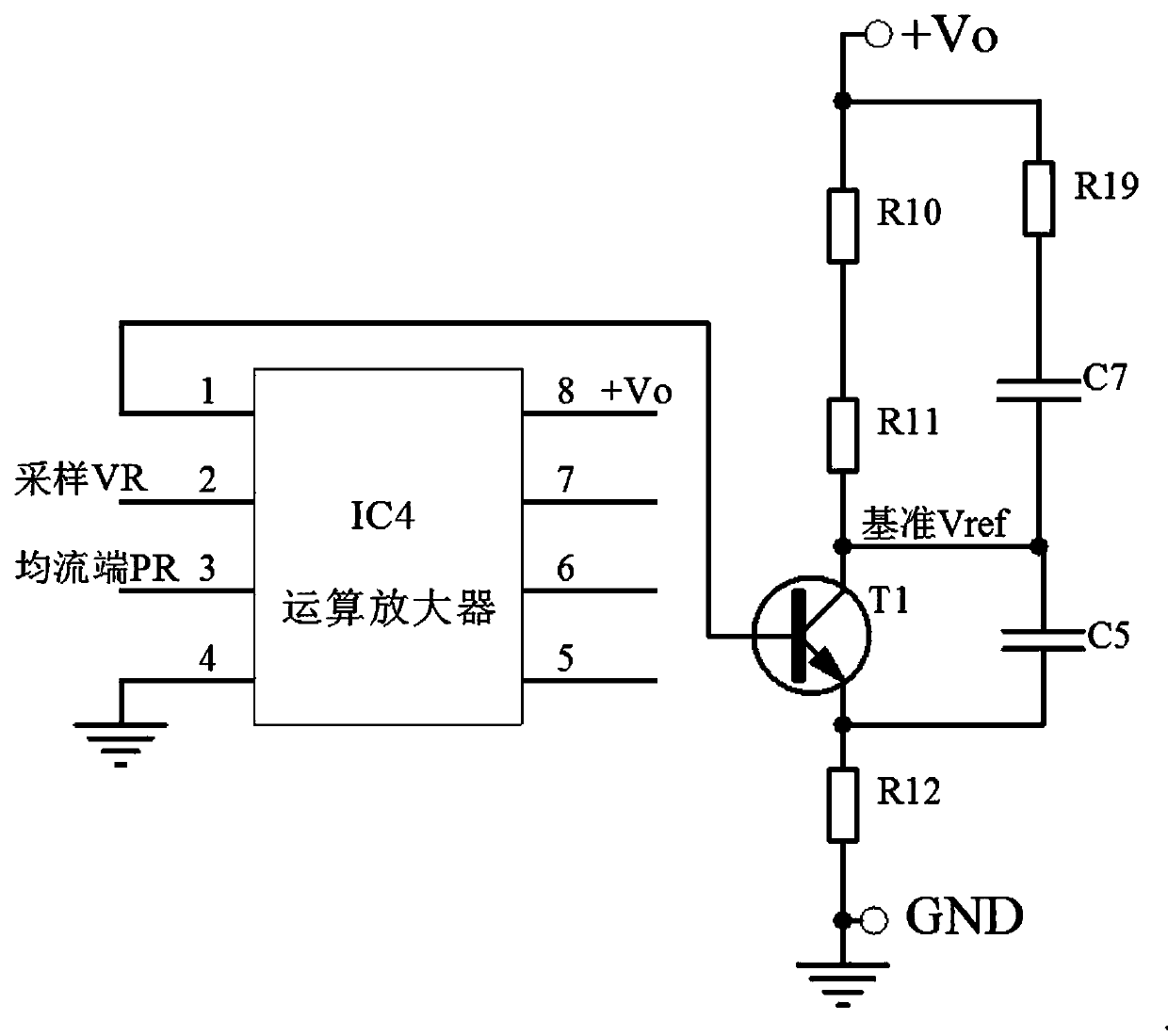
[0034]When power supply module 1 and power supply module 2 are connected in parallel, connect the current sharing terminals PR of the two power supply modules together, and the two power supply modules will sample the respective current sampling resistor R18, and convert the sampled current through the operational amplifier IC3 into For example, the voltage output from power module 1 to the current sharing terminal PR is 0.72V, while the voltage output from power module 2 to the current sharing terminal PR is 0.78V. The voltage of the power module with the largest output current at the current sharing terminal PR, due to the Terminal PR is connected to pin 6 of operational amplifier IC3 and pin 3 of operational amplifier IC4, and raises the voltage of pin 3 of input power module 1 operational amplifier IC4 to 0.78V. At this time, pin 2 of operational amplifier IC4 of power module 1 (input negative ) voltage 0.72V is compared with pin 3 (input positive) 0.78V of the operational ...


PUM


Abstract

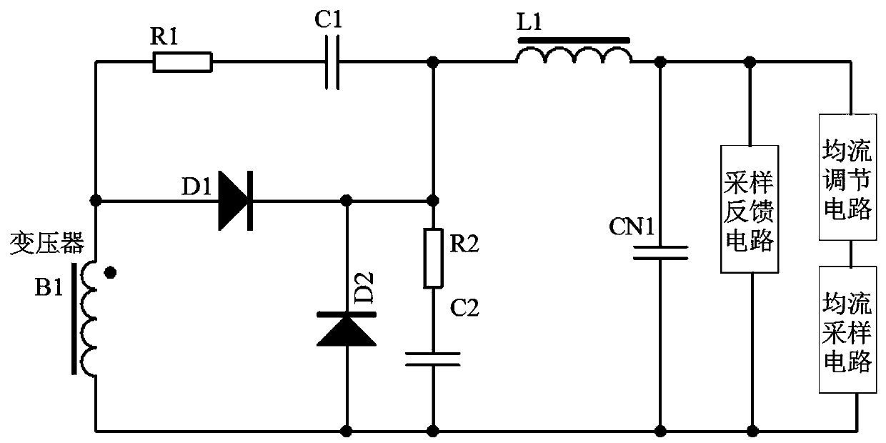
The invention discloses a circuit and method suitable for parallel connection of high-power switching power supplies, including a transformer. The front stage of the transformer is a commonly used active clamp or double forward. current sampling circuit, current equalization adjustment circuit, and sampling feedback circuit; the present invention reduces the current equalization error, reduces the reference error from ±1.5% to ±0.48%, improves the accuracy of multiple power supply modules in parallel current equalization, and improves the The closed-loop loop bandwidth and gain improve the reliability, stability, and transient response of the power module.

Description

technical field [0001] The invention belongs to the field of electronic appliances and relates to a plurality of high-power switching power supplies, in particular to a circuit and method suitable for parallel connection of high-power switching power supplies. Background technique [0002] With the improvement of various performances of semiconductors, the requirements for switching power supplies are getting higher and higher. High power density, high reliability, small size, and systematization are the mainstream development directions of switching power supplies. Single-power power supply modules are increasingly unable to meet the requirements. Now the requirements of the system level, the parallel connection of multiple high-power switching power supply modules has become the focus of the development of switching power supply technology. The power supply capacity can be expanded to achieve high efficiency, reduce costs, and realize the standardization and modularization...

Claims


Application Information

Patent Timeline
Patent Type & Authority Patents(China)
IPC IPC(8): H02M1/00
CPCH02M1/00H02M1/0003
Inventor 王勇刘吉海齐福淼
Owner TIANSHUI 749 ELECTRONICS
Learn More