
Liquid transmission control device and liquid transmission system

A technology of transmission control and liquid, which is applied in the direction of control/regulation system, flow control, non-electric variable control, etc. It can solve problems such as medical accidents, abnormal body functions of blood drawers, and inability to monitor the state of body fluid transmission, so as to avoid flow rate abnormal effect

Pending Publication Date: 2019-10-01
HEFEI BOE OPTOELECTRONICS TECH +1
View PDF8 Cites 3 Cited by
  • Summary
  • Abstract
  • Description
  • Claims
  • Application Information

AI Technical Summary

Problems solved by technology

[0003] At present, when the above-mentioned liquid transmission is performed in the existing technology, it is usually directly connected to the pipeline, and the status of the body fluid transmission cannot be monitored, which may cause the risk of medical accidents
For example, in the current conventional blood drawing / donating process, the blood flows out of the human body mainly through the pressure difference between the human body's blood pressure and the vacuum negative pressure in the blood collection bag. On the one hand, this conventional solution cannot automatically control the blood drawing speed according to the individual's physical fitness On the other hand, when the blood pressure in the blood pump tube stops flowing normally when the blood pumping process is abnormal, the medical staff cannot find out in time, and there is a risk of blood stagnation or backflow in the part of the blood drawn by the needle

Method used


Image

  • Liquid transmission control device and liquid transmission system
  • Liquid transmission control device and liquid transmission system
  • Liquid transmission control device and liquid transmission system

Examples


Embodiment Construction

[0044] In order to make the technical problems, technical solutions and advantages to be solved by the present invention clearer, the following will describe in detail with reference to the drawings and specific embodiments.

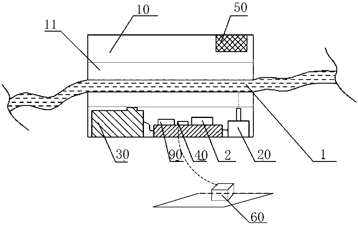
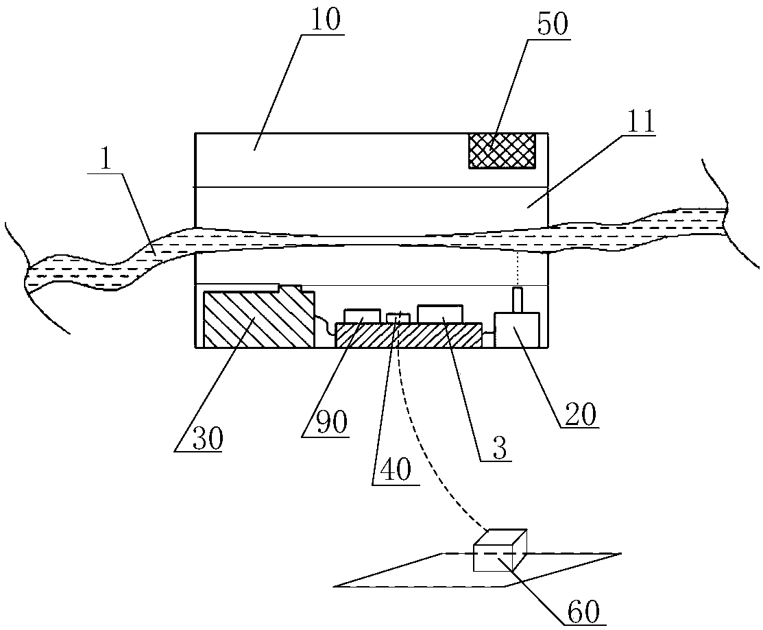
[0045] figure 1 It is a partial structural schematic diagram of the liquid transmission control device according to the embodiment of the present invention. refer to figure 1 As shown, the liquid delivery control device includes:

[0046] The pipeline carrier 10, the pipeline carrier 10 is configured to allow the pipeline 1 used for liquid transmission and soft material to pass through it, and the pipeline carrier 10 includes an accommodating space 11, the accommodating space 11 configured to accommodate at least part of the conduit 1;

[0047] A flow rate sensor 20, used to detect the flow rate of liquid transmission in the pipeline 1;

[0048] The adjustment structure 30 is used to adjust the flow rate of the liquid transmission in the pipeline 1 b...


PUM


Abstract

The invention provides a liquid transmission control device and a liquid transmission system. The device comprises a pipeline bearing member, a flow rate sensor, an adjustment structure and a controller. The pipeline bearing member is designed to allow pipelines made from soft materials and used for liquid transfer to be arranged therein, the pipeline bearing member includes an accommodating space, and the accommodating space is used for accommodating at least one part of the pipelines; the flow rate sensor is used for detecting the flow rate of liquid transmission in the pipelines; the adjustment structure is used for adjusting the cross-sectional areas of the pipelines arranged in the accommodating space so as to adjust the flow rate of liquid transmission in the pipelines; the controller is used for outputting a control signal to the adjustment structure according to the flow rate detected by the flow rate sensor, so that the adjustment structure adjusts the cross-sectional areas ofthe pipelines arranged in the accommodating space. The device can monitor the condition of in-vitro and in-vivo liquid transmission and control the liquid transmission speed timely to avoid medical accidents caused by abnormal flow rates.

Description

technical field [0001] The invention relates to the technical field of medical equipment, in particular to a liquid transmission control device and a liquid transmission system. Background technique [0002] The transmission of blood or liquid medicine between the body and the outside of the body is very common in current medical treatment. It is necessary to inject medicinal liquid into the human body. [0003] At present, when the above-mentioned liquid transmission is performed in the existing technology, it is usually directly connected to the pipeline, and the status of the body fluid transmission cannot be monitored, which may cause a risk of medical accidents. For example, in the current conventional blood drawing / donating process, the blood flows out of the human body mainly through the pressure difference between the human body's blood pressure and the vacuum negative pressure in the blood collection bag. On the one hand, this conventional solution cannot automatic...

Claims


Application Information

Patent Timeline
IPC IPC(8): A61M5/168A61M5/172
CPCA61M5/16813A61M5/16886A61M5/142A61M5/16881A61M5/172A61M2205/18A61M2205/3553A61M2205/505A61M2230/04A61M2230/50
Inventor 李朋黄炯章祯胡凌霄
Owner HEFEI BOE OPTOELECTRONICS TECH
Learn More