Anti-breakage and cut filter bottle structure based on chemical test

A technology for chemical test and suction filter bottle, which is applied to the field of suction filter bottle structure for preventing damage and cuts, can solve the problems of broken glass structure at the two bottle mouths, difficult to discharge outwards, and hidden safety hazards, and achieves improved functional characteristics, Reduce waste and improve anti-slip effect

Active Publication Date: 2021-06-15
绍兴市卓诚新材料有限公司
View PDF7 Cites 0 Cited by
  • Summary
  • Abstract
  • Description
  • Claims
  • Application Information

AI Technical Summary

Problems solved by technology

[0006] In order to solve the above-mentioned technical problems, the present invention provides a filter bottle structure based on chemical tests to prevent breakage and cuts, so as to solve the problem that the existing application of the filter bottle with the above-mentioned structure is similar to that of the top filter bucket in the chemical experiment process. When the solid-liquid mixture in the top suction filter funnel is drawn downward by air pressure, it is easy to form a negative pressure suction between the suction filter funnel and the top opening of the suction filter bottle, resulting in a negative pressure between the suction filter funnel and the inserted suction filter after the experiment is completed. The position of the top mouth of the filter bottle forms a strong pressure suction, which is not easy to separate. Excessive force will cause the glass structure of the two bottle mouths to break, which poses a safety hazard. Moreover, the suction filter chamber used for filtering inside the filter bucket is composed of filter holes. Therefore, there will be a large amount of reagent residue after suction filtration in the filter hole, which is not easy to discharge when collecting.

Method used


Image

  • Anti-breakage and cut filter bottle structure based on chemical test
  • Anti-breakage and cut filter bottle structure based on chemical test
  • Anti-breakage and cut filter bottle structure based on chemical test

Examples


Embodiment

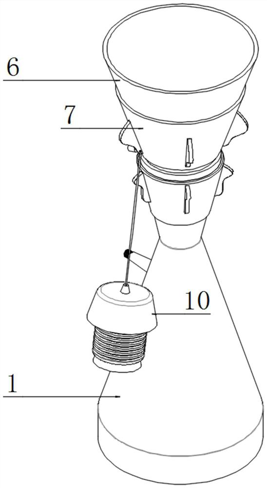
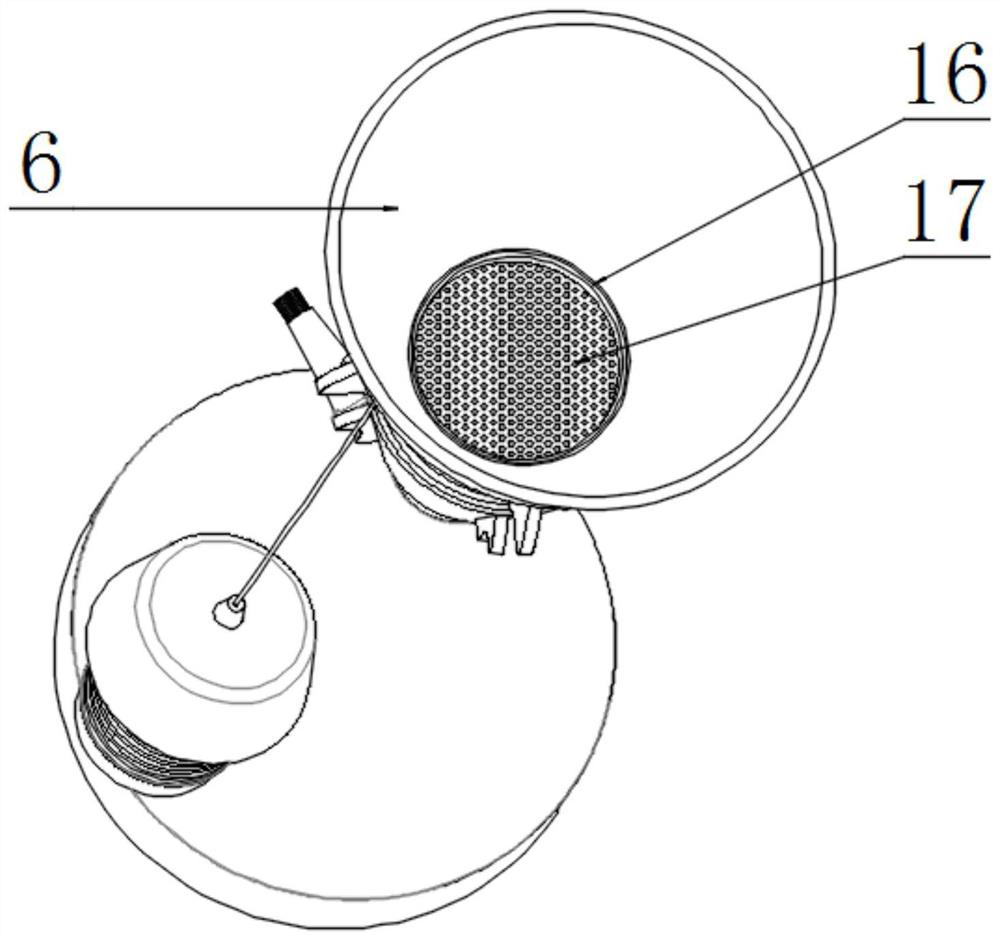
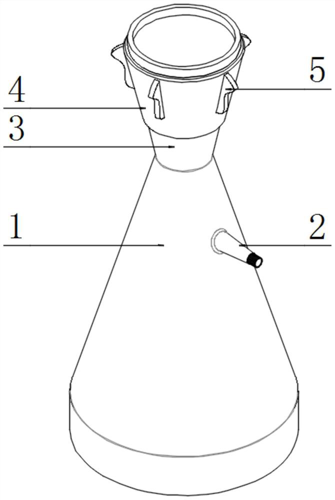
[0033] as attached figure 1 to attach Figure 9 Shown:

[0034] The present invention provides a damage-proof and cut-resistant suction filter bottle structure based on chemical tests, including a bottom bottle 1, a suction pump connecting pipe 2, a suction filter bucket nozzle 3, a nozzle protection ring 4, a first handle 5, and a suction filter bucket 6. Filter bucket retaining ring 7, second handle 8, pull cord 9, pressure capsule cover 10, pressure capsule cavity 11, perforation 12, retaining seat 13, rubber ring 14, buckle 15, suction filter cavity 16 and fine filter hole 17; The bottom bottle 1 is connected to the external suction pump through the suction pump connecting pipe 2 penetrated by one side, and a suction filter funnel 6 with a tapered funnel structure is inserted into the suction filter funnel cover 3 on the top of the bottom bottle 1 The pressure bag cover 10 is a hollow cavity structure, and its bottom is connected with a cylindrical corrugated cavity-shap...


PUM


Abstract

The invention provides a suction filter bottle structure based on a chemical test to prevent breakage and cut, including a suction filter bucket, a filter bucket guard ring, a second handle, a pull cord, a pressure capsule cover, a pressure capsule cavity, perforations, a retaining seat, a rubber ring, Buckle, suction filter cavity and fine filter hole; the bottom bottle is connected to the external pump through the suction pump connection pipe through one side, and a conical funnel is inserted into the suction filter funnel sleeve on the top of the bottom bottle cavity structure suction filter funnel; the pressure capsule cover is a hollow cavity structure, the bottom of which is connected with a cylindrical corrugated cavity-shaped pressure capsule cavity, thus forming a compressed air bag seat by the pressure capsule cover and the pressure capsule cavity, The method of manual air outlet is adopted to discharge the remaining material residue in the suction filter cavity used to filter the medicine at the bottom of the suction filter cavity after suction filtration to reduce waste. The suction filter cavity is cleaned, so the functional structure has been improved.

Description

technical field [0001] The invention belongs to the technical field of laboratory appliances, and more specifically relates to a damage-resistant and cut-resistant suction filter bottle structure based on chemical tests. Background technique [0002] During experiments in the fields of chemistry, biology, and medicine, it is often necessary to filter liquids to obtain high-purity solutions or solids. Vacuum filtration is a common solid-liquid separation method. It is a method of accelerating water filtration by using the negative pressure caused by pumping. Generally, it means that under the action of external forces such as driving force, the solution passes through the filter medium to retain solid particles and other manipulation of matter. [0003] Chinese patent application number CN201720802335.4 relates to and discloses a suction filtration bottle and a vacuum suction filtration device. The basic description in the abstract of the specification is: the filter bottle...

Claims


Application Information

Patent Timeline
Patent Type & Authority Patents(China)
IPC IPC(8): B01D29/085B01D29/94B01D35/14
CPCB01D29/085B01D29/94B01D35/14
Inventor 张景仁
Owner 绍兴市卓诚新材料有限公司
Why Eureka
Try Eureka