Stirrer for foaming in laboratory
A laboratory and agitator technology, applied in the direction of mixer accessories, chemical instruments and methods, mixers with rotating containers, etc., can solve the problems of large space occupation, inconvenient installation, disassembly and maintenance, and limitation of mixing range, and achieve the goal of reducing space Occupancy, easy disassembly and maintenance, and the effect of improving mixing efficiency
- Summary
- Abstract
- Description
- Claims
- Application Information
AI Technical Summary
Problems solved by technology
Method used
Image
Examples
Embodiment 1
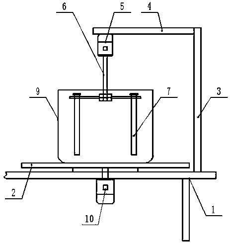
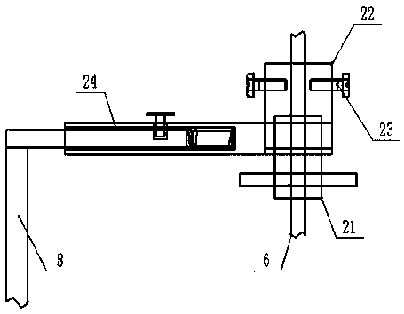
[0015] Embodiment 1: see figure 1 , figure 2 , image 3 , Figure 4 Now, a mixer for laboratory foaming provided by the present invention will be described, including an experimental table body 1, a processing and placing platform 2 is provided on the upper side of the experimental table body 1, and the upper end of the experimental table body 1 is located at A vertical support frame 3 is provided next to the position of the processing and placement platform 2, and the top of the vertical support frame 3 is fixedly connected with a horizontal support frame 4, and the lower side of the non-fixed end of the horizontal support frame 4 is provided with a first rotating motor 5 , the vertically downward output shaft end of the first rotating motor 5 is connected with a rotating shaft 6 through a coupling, the non-connecting end of the rotating shaft 6 is provided with a stirring rod 7, and the position side of the rotating shaft 6 is provided with a There is a cleaning rack 8, ...
Embodiment 2
[0016] Example 2: see figure 1 , the agitator for laboratory foaming provided by the present invention will now be described. The experimental table body 1 includes a desktop board and legs provided at the four corners of the lower end of the desktop board, and the top of the desktop board is fixed with a ring The supporting frame, the middle side of the lower end of the processing and placing table 2 is flexibly connected with the upper end of the annular supporting frame, the processing and placing table 2 is set as a disc shape, and the edge of the upper end of the processing and placing table 2 is evenly arranged Positioning cylinders, the positioning cylinders are all arranged along the radius direction of the horizontal cross section of the processing and placement table 2, the piston rod ends of the positioning cylinders are all set corresponding to the central part of the processing and placement table 2, and the piston rod ends of the positioning cylinders A positioni...
Embodiment 3
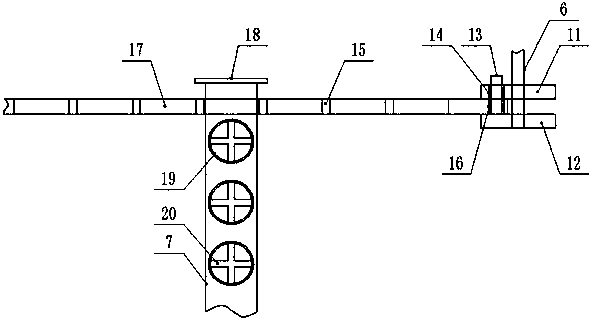
[0017] Embodiment 3: see figure 1 , image 3 Now, a stirrer for laboratory foaming provided by the present invention is described. The non-connecting end of the rotating shaft 6 is covered with a ring frame, and the ring frame includes an upper ring frame 11 and a lower ring frame 12. The inner end of the lower ring frame 12 is connected with the outer end of the rotating shaft 6, the upper edge of the lower ring frame 12 is evenly provided with clamping posts 13, and the upper ring frame 11 is located at the position of the lower ring frame 12. Above, the inner port diameter of the upper ring frame 11 is greater than the cross-sectional diameter of the rotating shaft 6, and the edge of the upper ring frame 11 is uniformly provided with a second bayonet 14, and the stirring rod 7 is connected to the rotating shaft. 6 are vertically spaced and arranged in parallel with each other, and a horizontal connecting frame 15 is uniformly arranged between the upper ring frame 11 and th...
PUM
 Abstract
Description
Claims
Application Information
 - R&D
- Intellectual Property
- Life Sciences
- Materials
- Tech Scout
- Unparalleled Data Quality
- Higher Quality Content
- 60% Fewer Hallucinations
Browse by: Latest US Patents, China's latest patents, Technical Efficacy Thesaurus, Application Domain, Technology Topic, Popular Technical Reports.
© 2025 PatSnap. All rights reserved.Legal|Privacy policy|Modern Slavery Act Transparency Statement|Sitemap|About US| Contact US: help@patsnap.com


