
Intelligent ring throwing machine tool and control method thereof

An intelligent ring, machine tool technology, applied in the direction of grinding machine parts, grinding automatic control device, workpiece feed movement control, etc., can solve problems such as difficult control or correction, polishing disc shape error, etc., to improve the stability , The effect of ensuring milling accuracy and reducing system errors

Pending Publication Date: 2019-10-01
LASER FUSION RES CENT CHINA ACAD OF ENG PHYSICS +1
View PDF1 Cites 7 Cited by
  • Summary
  • Abstract
  • Description
  • Claims
  • Application Information

AI Technical Summary

Problems solved by technology

[0005] In view of this, the present invention provides an intelligent ring polishing machine tool, which solves the problem that the shape error of the polishing disc is difficult to control or correct in the prior art

Method used

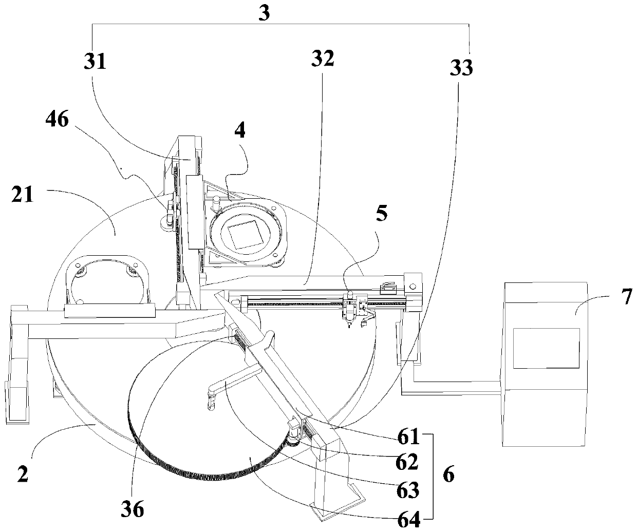
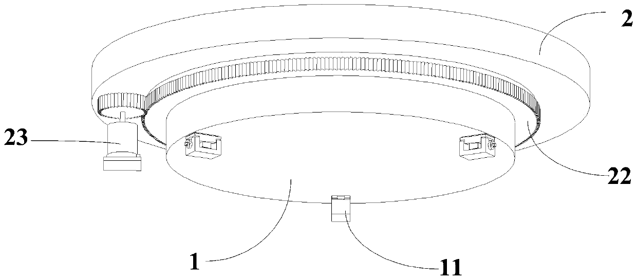
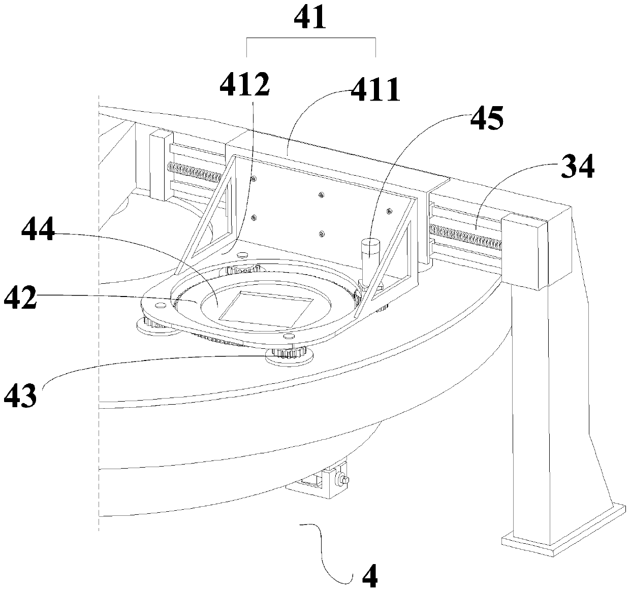

Image

  • Intelligent ring throwing machine tool and control method thereof
  • Intelligent ring throwing machine tool and control method thereof
  • Intelligent ring throwing machine tool and control method thereof

Examples


Embodiment Construction

[0075] The following will clearly and completely describe the technical solutions in the embodiments of the present invention with reference to the accompanying drawings in the embodiments of the present invention. Obviously, the described embodiments are only some, not all, embodiments of the present invention. Based on the embodiments of the present invention, all other embodiments obtained by persons of ordinary skill in the art without making creative efforts belong to the protection scope of the present invention.

[0076] The embodiment of the invention discloses an intelligent ring polishing machine tool, which solves the problem that the shape error of the polishing disk is difficult to control or correct in the prior art.

[0077] See attached figure 1 , the present invention provides an intelligent ring throwing machine tool, comprising:

[0078] base 1,

[0079] The turntable 2, the top of the base 1 supports the bottom of the turntable 2, and is rotatably connect...


PUM


Abstract

The invention relates to an intelligent ring throwing machine tool. The intelligent ring throwing machine tool comprises a base, wherein the top of the base is supported at the bottom of a rotary table; a layer of asphalt mastic is poured on the top surface of the rotary table so as to form a polishing disk; a multi-station bridge mechanism is erected on the top of the rotary table; an element machining station, a polishing disk detection station and a disk correcting station are correspondingly arranged in positions of multiple cross beams of the multi-station bridge mechanism; a first linearsliding guide rail is arranged on the first cross beam which corresponds to the element machining station, and an element machining device can be connected with the first linear sliding guide rail ina sliding mode; an air flotation linear guide rail is arranged on the second cross beam which corresponds to the polishing disk detection station, and a polishing disk detection device can be connected with the air flotation linear guide rail in the sliding mode; a second linear sliding guide rail is arranged on the third cross beam which corresponds to the disk correcting station, and a polishing disk correcting device can be connected with the second linear sliding guide rail in the sliding mode; and the element machining device, the polishing disk detection device and the polishing disk correcting device are all electrically connected with a control terminal, and element machining, polishing disk detection and polishing disk correcting procedures are preset in the control terminal.

Description

technical field [0001] The invention relates to the technical field of optical processing, and more specifically relates to an intelligent ring polishing machine tool and a control method thereof. Background technique [0002] Ring polishing (referred to as ring polishing) is one of the key technologies for processing large-diameter flat optical components. The ring polishing machine usually uses large-size, high-thermal-stability natural granite to make the polishing disc base plate, and the surface of the base plate is cast with a ring-shaped asphalt adhesive layer as the polishing disc. The ring surface of the asphalt polishing disc is provided with a correction disc and a workpiece disc in turn, and a gear synchronous belt is arranged on the circumferential side of the correction disc and the workpiece disc, and the two are respectively driven by a pair of gears and a driving gear belt to achieve uniform rotation. The correction disc is used to correct and control the s...

Claims


Application Information

Patent Timeline
Patent Type & Authority Applications(China)
IPC IPC(8): B24B13/00B24B13/005B24B13/01B24B41/02B24B51/00B24B47/12B24B49/00B24B53/12
CPCB24B13/00B24B13/0055B24B13/01B24B41/02B24B51/00B24B47/12B24B49/00B24B53/12Y02P70/10
Inventor 廖德锋许乔陈健陈福恭谢瑞清赵世杰周炼陈贤华张清华张飞虎王健
Owner LASER FUSION RES CENT CHINA ACAD OF ENG PHYSICS
Learn More