
Battery mounting structure and car

An installation structure and battery technology, applied in the field of vehicles, can solve the problems of electrochemical corrosion, unstable connection, low strength and rigidity, etc., and achieve the effect of preventing electrochemical corrosion and ensuring stable connection.

Pending Publication Date: 2019-10-01
BYD CO LTD
View PDF0 Cites 1 Cited by
  • Summary
  • Abstract
  • Description
  • Claims
  • Application Information

AI Technical Summary

Problems solved by technology

However, since the existing car body structural parts and fasteners (such as screws and nuts) are mostly made of carbon steel or other high-strength steel materials, and there is a large potential difference between magnesium alloys, aluminum alloy materials and carbon steel materials, magnesium The alloy battery tray (or aluminum alloy battery tray) is prone to electrochemical corrosion after it is fixedly connected to the car body structure (such as the car body sheet metal), which will lead to a decrease in the performance of the battery tray
At the same time, compared with steel materials, magnesium alloy and aluminum alloy materials have lower strength and rigidity, so the connection will be unstable

Method used


Image

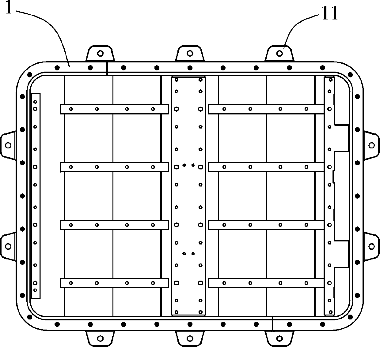
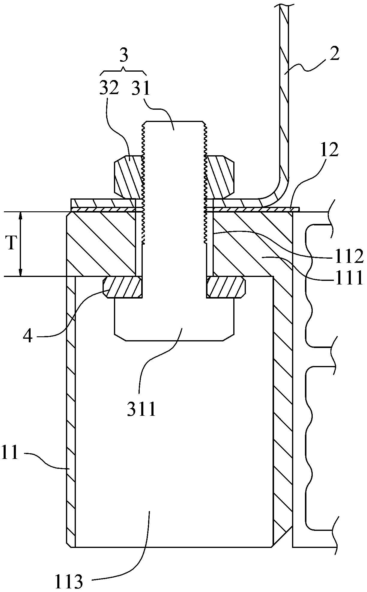
  • Battery mounting structure and car
  • Battery mounting structure and car

Examples


Embodiment Construction

[0024] Embodiments of the invention are described in detail below, examples of which are illustrated in the accompanying drawings. The embodiments described below by referring to the figures are exemplary and are intended to explain the present invention and should not be construed as limiting the present invention.

[0025] In describing the present invention, it should be understood that the terms "center", "longitudinal", "transverse", "length", "width", "thickness", "upper", "lower", "front", " Back", "Left", "Right", "Vertical", "Horizontal", "Top", "Bottom", "Inner", "Outer", "Clockwise", "Counterclockwise", "Axial", The orientation or positional relationship indicated by "radial", "circumferential", etc. is based on the orientation or positional relationship shown in the drawings, and is only for the convenience of describing the present invention and simplifying the description, rather than indicating or implying the referred device or element Must be in a particular ...


PUM


Abstract

The invention discloses a battery mounting structure. The battery mounting structure comprises a battery tray used for containing a battery, a car body metal plate for fixing the battery tray and a fastening part used for connecting the battery tray with the car body metal plate. The battery tray is a magnesium alloy battery tray or aluminum alloy battery tray, a first isolation coating is arranged between the battery tray and the car body metal plate, and an isolation gasket is arranged between the battery tray and the fastening part. The first isolation coating is arranged for isolating thebattery tray and the car body metal plate, the electrochemical corrosion between the battery tray and the car body metal plate is prevented, meanwhile, the isolation gasket is used for preventing theelectrochemical corrosion between the fastening part and the battery tray, the battery mounting structure is stable in connection, and the electrochemical corrosion between the battery tray and the car body metal plate and between the battery tray and the fastening part is solved.

Description

technical field [0001] The invention relates to the technical field of vehicles, in particular to a battery installation structure and an automobile. Background technique [0002] In order to achieve the goal of reducing the weight of automobiles, the prior art recommends the use of lightweight metals—magnesium alloys or aluminum alloys—as battery tray materials. However, since the existing car body structural parts and fasteners (such as screws and nuts) are mostly made of carbon steel or other high-strength steel materials, and there is a large potential difference between magnesium alloys, aluminum alloy materials and carbon steel materials, magnesium Alloy battery trays (or aluminum alloy battery trays) are prone to electrochemical corrosion after they are fixedly connected to the car body structure (such as car body sheet metal), which will lead to a decrease in the performance of the battery tray. At the same time, compared with steel materials, magnesium alloy and al...

Claims


Application Information

Patent Timeline
Patent Type & Authority Applications(China)
IPC IPC(8): B60R16/04
CPCB60R16/04
Inventor 宫清郭强文丹华李卫国霍皓皓
Owner BYD CO LTD
Learn More