Shear wall template structure and construction method

A shear wall and formwork technology, applied in the direction of formwork/formwork/work frame, formwork/formwork/work frame connector, wall, etc., can solve problems such as increased workload, difficult manual movement, and impact on turnover times. , to achieve the effect of reducing the punching process, ensuring the appearance quality, and increasing the number of turnovers

Inactive Publication Date: 2019-10-01
CHINA FIRST METALLURGICAL GROUP
View PDF12 Cites 8 Cited by
  • Summary
  • Abstract
  • Description
  • Claims
  • Application Information

AI Technical Summary

Problems solved by technology

like Figure 7 As shown, during the second turnover reinforcement, the formwork will be drilled again, and the eyelets of the previous formwork will be blocked at the same time, and often the sealing is not strict, and it is easy to leak grout, resulting in concrete flow, trachoma, and honeycomb. , pockmarks, etc., affect the appearance quality of concrete
After many turnovers, the formwork is full of holes, which not only affects the quality of concrete molding, but also affects the number of turnovers
Moreover, drilling and blocking of the formwork will increase the workload and delay the construction period.
There is also a combined steel formwork for installation. The steel formwork is heavy and difficult to move manually. Sometimes it needs to be hoisted and installed, resulting in increased mechanical costs. At the same time, the steel formwork does not absorb water, and it is difficult to discharge air bubbles during concrete construction. The concrete is prone to air bubbles, which affects the concrete. Appearance Quality

Method used


Image

  • Shear wall template structure and construction method
  • Shear wall template structure and construction method
  • Shear wall template structure and construction method

Examples


Embodiment Construction

[0032] In order to better understand the present invention, the technical solutions of the present invention will be further described below in conjunction with embodiments and drawings.

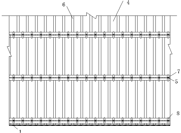
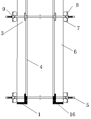
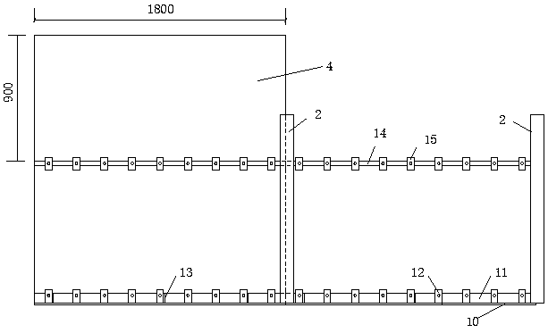
[0033] A shear wall formwork structure, which is mainly formed by splicing several formwork 4, the bottom row of formwork 4 is erected on a shaped bottom clamp 1, the shaped bottom clamp 1 is L-shaped, and the shaped bottom clamp A number of first locking plates 12 are evenly arranged along the length of the inner side of the member 1, and each first locking plate 12 is provided with a pair of bolt holes; the shaped bottom clamping member 1 includes a horizontally arranged presser foot plate 10 and a vertical A straightly arranged first bead 11, the first bead 11 and the presser foot plate 10 are connected by nails into an L-shape (that is, an angle steel structure), and the first locking plate 12 is vertically arranged on the inner side of the first bead 11; A triangular stiffening plate 13 fo...


PUM


Abstract

The invention belongs to the field of housing construction and utility tunnel construction, and particularly relates to a shear wall template structure. The shear wall template structure is mainly formed by splicing a plurality of templates, and a row of templates located below are arranged on a setting bottom clamping part which is of an L type; the inner side of the setting bottom clamping partis provided with a plurality of first locking plates in the length direction uniformly, and each first locking plate is provided with a split bolt hole; a setting middle clamping part is arranged between the templates of the upper and lower adjacent layers, and comprises a second long depression bar of which one side is provided with a plurality of second locking plates in the length direction uniformly; each second locking plate is provided with a split bolt hole; and the templates on the both sides of the shear wall are fixed to the position of each split bolt hole through pull screws. According to the shear wall template structure, the drilling procedures of the templates are reduced, and the cost is saved; meanwhile the construction period is shortened, and the construction process issimple; and the shear wall template structure is easy to operate by workers.

Description

Technical field [0001] The invention belongs to the field of house construction and pipe gallery construction, and specifically relates to a shear wall formwork structure and a construction method. Background technique [0002] At present, the installation of shear wall formwork in civil buildings mostly adopts the combined installation form of wooden formwork, square wood and steel pipe, or uses a fixed formwork composed of wooden formwork and square wood. During installation and reinforcement, holes will be drilled on the template, and the tension screw will be used for reinforcement. Such as Figure 7 As shown, during the second turnover reinforcement, the formwork will be drilled, and the last formwork must be sealed at the same time, and the sealing is often not tight, which is easy to leak, causing concrete flow, sand holes, and honeycombs. , Pitted surface, etc., affect the appearance quality of concrete. After many turnovers, the formwork is riddled with holes, which not...

Claims


Application Information

Patent Timeline
Patent Type & Authority Applications(China)
IPC IPC(8): E04G11/08E04G17/065E04B2/84
CPCE04G11/08E04G17/0652E04B2/84
Inventor 刘奎刘明周廖红玉余珊孙广宏桂祁东黄达锴方慧琴
Owner CHINA FIRST METALLURGICAL GROUP
Why Eureka
Try Eureka