Oil-gas suspension cylinder and vehicle

A technology of oil-pneumatic suspension and cylinder, which is applied in the direction of springs, shock absorbers, spring/shock absorbers, etc., can solve the problems of small damping force of oil-pneumatic springs, reduced service life, and oil is easy to be carried out, so as to ensure stability Effect

Pending Publication Date: 2019-10-01
LOUDI ZHONGXING HYDRAULIC COMPONENTS CO LTD
View PDF0 Cites 9 Cited by
  • Summary
  • Abstract
  • Description
  • Claims
  • Application Information

AI Technical Summary

Problems solved by technology

[0004] 1) The damping force of the oil-gas spring is too small at low speed, and the damping force is too high at high speed, which cannot achieve a stable and comfortable effect
[0005] 2) Exhaust is inconvenient, and the oil-gas ratio cannot be precisely controlled
[0006] 3) When the temperature is too high during operation, the oil-gas mixture will cause cavitation to the seal and the surface of the parts, and the service life will be reduced
[0007] 4) The oil is easily carried out when charging and deflated, causing the damping curve and stiffness curve to deviate from the design requirements

Method used


Image

  • Oil-gas suspension cylinder and vehicle
  • Oil-gas suspension cylinder and vehicle
  • Oil-gas suspension cylinder and vehicle

Examples


Embodiment Construction

[0035] In order to have a clearer understanding of the above objects, features and advantages of the present invention, the present invention will be further described in detail below in conjunction with the accompanying drawings and specific embodiments. It should be noted that, in the case of no conflict, the embodiments of the present application and the features in the embodiments can be combined with each other.

[0036] In the following description, many specific details are set forth in order to fully understand the present invention. However, the present invention can also be implemented in other ways different from those described here. Therefore, the protection scope of the present invention is not limited by the specific details disclosed below. EXAMPLE LIMITATIONS.

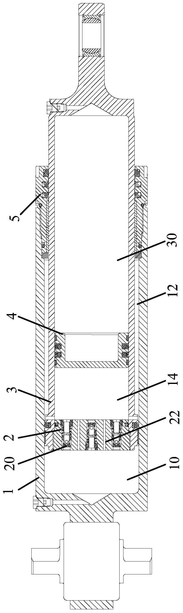
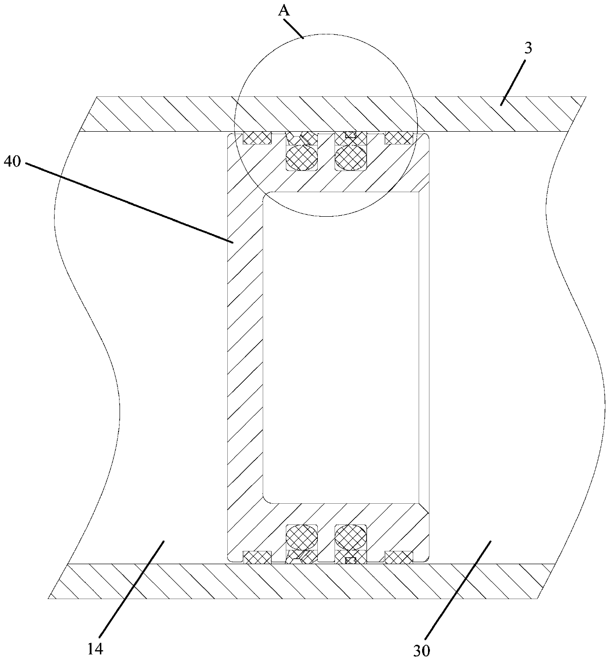
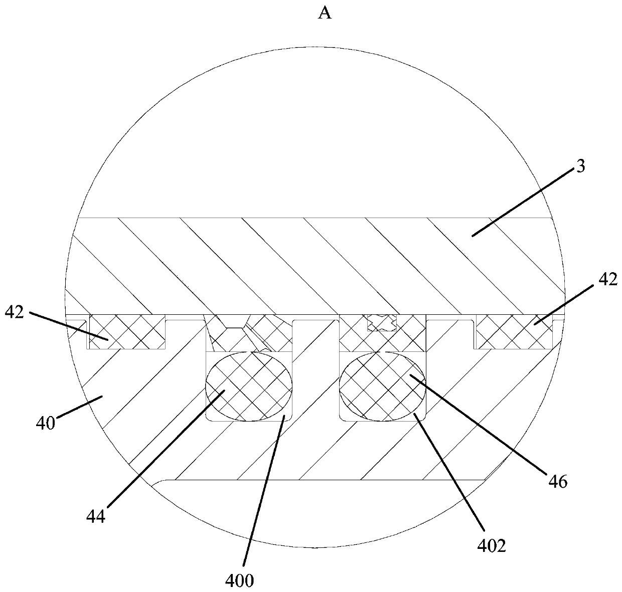
[0037] Refer below Figure 1 to Figure 5 Some embodiments according to the invention are described.

[0038] Such as Figure 1 to Figure 5 As shown, according to an embodiment of the present inventi...


PUM


Abstract

The invention provides an oil-gas suspension cylinder and a vehicle. The oil-gas suspension cylinder comprises a cylinder barrel, a throttling piston, a piston rod and a pneumatic piston, wherein thethrottling piston is arranged in the cylinder barrel, and is used for partitioning the space in the cylinder barrel into a roded cavity and a rodless cavity; the piston rod is located in the roaded cavity, and connected with the throttling piston; a piston rod barrel cavity is formed in the piston rod; the pneumatic piston is arranged in the piston rod barrel cavity slidably; the piston rod barrelcavity is partitioned by the pneumatic piston into a throttling cavity and a gas cavity independent of each other; and the throttling cavity is adjacent with the rodless cavity and communicates withthe roded cavity. Due to the technical scheme of the oil-gas suspension cylinder, oil-gas separation in the oil-gas suspension cylinder is effectively achieved, so that damping force in two directionsin the oil-gas suspension cylinder is more balanced, and the driving stability of the vehicle can be kept easily; the oil-gas ratio can also be accurately controlled, inflating and deflating are moreconvenient and faster, and maintaining is convenient; and cavitation by mixed gas in oil liquid on sealing pieces and parts can also be eliminated, and the service life of the oil-gas suspension cylinder is prolonged.

Description

technical field [0001] The invention relates to the technical field of vehicles, in particular to an oil-pneumatic suspension cylinder and a vehicle. Background technique [0002] The oil-gas suspension cylinder (oil-gas spring) is a damping mechanism that uses oil to transmit pressure and uses inert gas as the spring medium. It is widely used due to its advantages of stiffness, damping nonlinearity, large unit energy storage ratio, and compact structure. . The existing oil-gas spring structure mainly adopts oil-gas mixture. The inside of the oil cylinder is filled with oil-gas mixture. There are throttle holes and check valves between the rod cavity and the rodless cavity. When the vehicle is running, the oil-gas mixture is in the throttle hole and check valve. The flow between them generates damping force and achieves the effect of vibration reduction. [0003] The existing oil-gas spring mainly has the following disadvantages: [0004] 1) The damping force of the oil-g...

Claims


Application Information

Patent Timeline
Patent Type & Authority Applications(China)
IPC IPC(8): F16F9/19F16F9/32F16F9/34F16F9/36
CPCF16F9/19F16F9/3214F16F9/3405F16F9/368
Inventor 王亮陈兵兵
Owner LOUDI ZHONGXING HYDRAULIC COMPONENTS CO LTD
Why Eureka
Try Eureka