
High-performance mechanical coupling test system and method for electric drive axle power assemblies

A powertrain and testing system technology, applied in the testing of mechanical components, testing of machine/structural components, measuring devices, etc., can solve problems such as high testing costs and achieve the effect of simple structural solutions

Pending Publication Date: 2019-10-01
SUZHOU YINGTEMO AUTOMOBILE TECH CO LTD
View PDF3 Cites 2 Cited by
  • Summary
  • Abstract
  • Description
  • Claims
  • Application Information

AI Technical Summary

Problems solved by technology

[0006] Under the above technical background, based on the inventor's years of research and development experience in the field of automotive drive axle powertrain testing, the level of theoretical knowledge he has mastered, and in-depth research on the structure of the electric drive axle powertrain, he decided to propose a new electric drive Bridge powertrain testing ideas to solve the core problem of high testing costs

Method used


Image

  • High-performance mechanical coupling test system and method for electric drive axle power assemblies
  • High-performance mechanical coupling test system and method for electric drive axle power assemblies
  • High-performance mechanical coupling test system and method for electric drive axle power assemblies

Examples


Embodiment 1

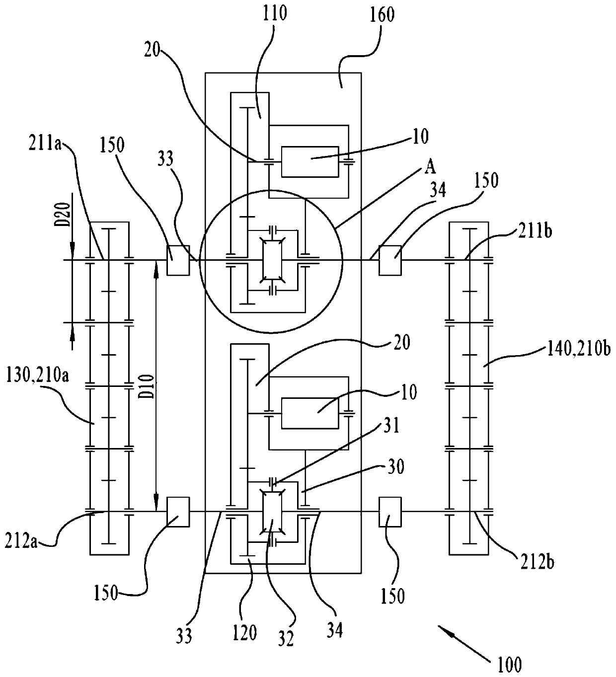
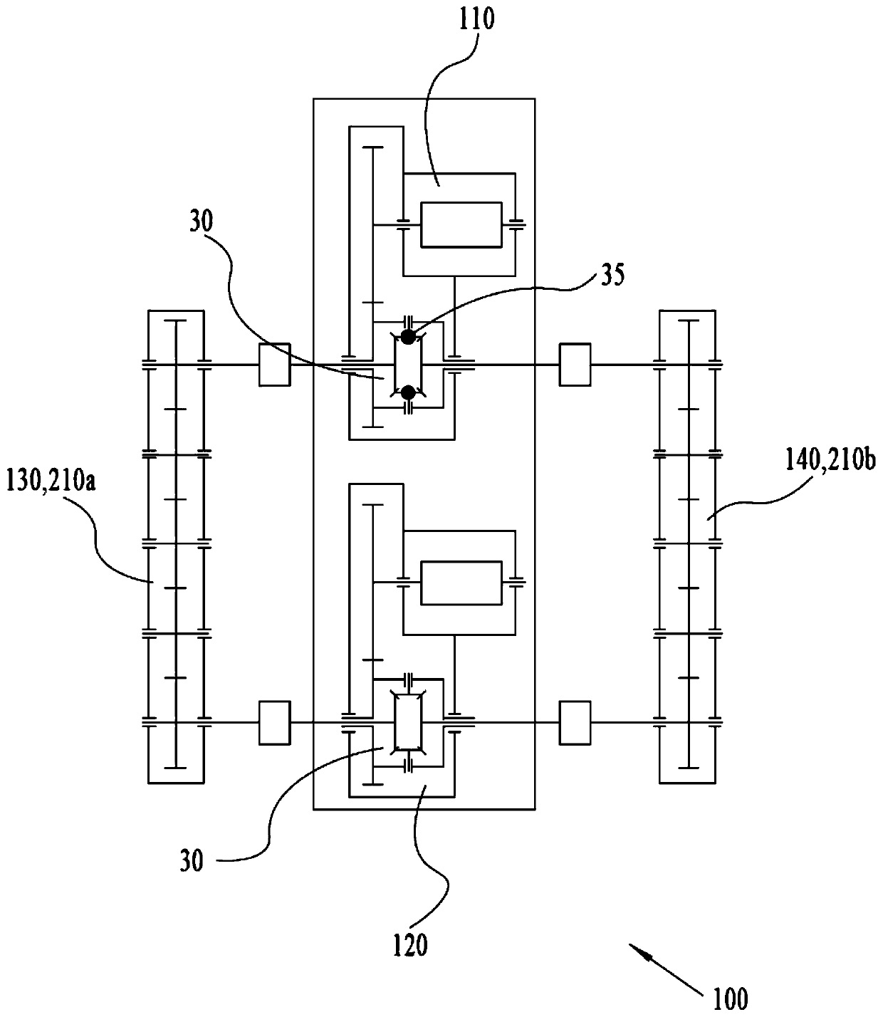
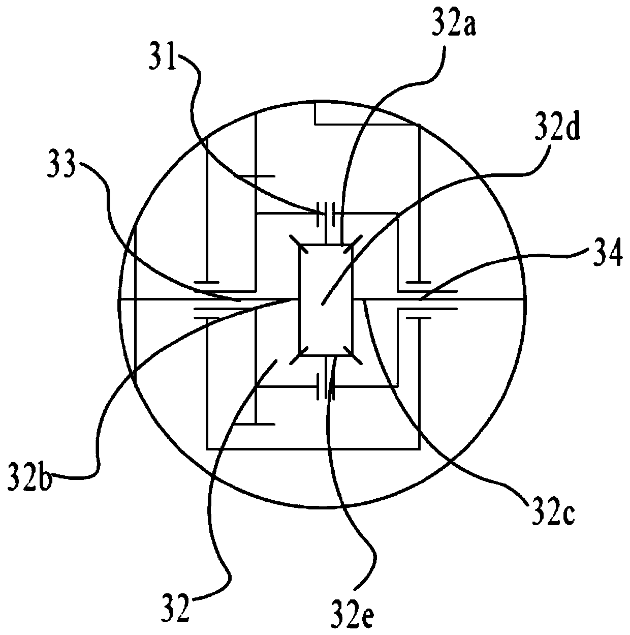
[0045] Example 1: see figure 1 and figure 2 A high-efficiency test system 100 for an electric drive axle power assembly shown includes a power supply (not shown in the figure) and a first electric drive axle power assembly 110 and a second electric drive axle power assembly 120, each of which The drive axle power assembly 110,120 includes the motor 10, the transmission 20 and the differential gear 30 driven and controlled by a variable frequency controller, please refer to further image 3 As shown, the differential 30 includes a power input end 31 connected to the power output end of the transmission 20, a differential gear assembly 32, and a first power output end 33 and a second power output end 34 that are on the same axis and distributed in the left and right directions. After each electric drive axle power assembly of the present embodiment is assembled and applied to a car, its first power output end 31 and second power output end 32 can be connected to the left wheel...

Embodiment 2

[0065] Embodiment 2: the remaining technical solutions of this embodiment 2 are the same as those of embodiment 1, the only difference is: please refer to Figure 4 As shown, in the second embodiment, both the first gear box 210a and the second gear box 210b adopt a three-stage transmission shaft bevel gear transmission connection structure.

Embodiment 3

[0066] Embodiment 3: the remaining technical solutions of this embodiment 3 are the same as those of embodiment 1, the only difference being: please refer to Figure 5 As shown, in this embodiment 3, the first transmission device 130 adopts the first sprocket transmission structure 230a, the second transmission device 140 adopts the second sprocket transmission structure 230b, and the first sprocket transmission structure 230a includes The first sprocket 231a of the first power output end 33 of the first electric drive axle power assembly 110 and the second sprocket 232a fixed on the first power output end 33 of the second electric drive axle power assembly 120, the first chain The wheel 231a and the second sprocket 232a adopt the first chain 233a for meshing transmission; the second sprocket transmission structure 230b includes the first sprocket 231b and The second sprocket 232b fixedly mounted on the second power output end 34 of the second electric drive axle power assembl...


PUM


Abstract

The invention discloses a high-performance mechanical coupling test system and method for electric drive axle power assemblies. The first power output end of the first electric drive axle power assembly is in transmission connection with one transmission device; the second power output end of the first electric drive axle power assembly is in transmission connection with the other transmission device; the first power output end of the second electric drive axle power assembly is in transmission connection with one transmission device; the second power output end of the second electric drive axle power assembly is in transmission connection with the other transmission device; and the high-performance mechanical coupling test system further comprises a first variable frequency control motorand a second variable frequency control motor. The test environments of the electric drive axle power assemblies under various different driving conditions can be simulated according to different compensation schemes, so that the relatively complete comprehensive performance evaluation of the electric drive axle power assemblies is realized.

Description

technical field [0001] The invention belongs to the testing technology of an automobile drive axle assembly, and in particular relates to a high-performance towing test system and a testing method for an electric drive axle power assembly. Background technique [0002] Those skilled in the art know that the differential of the automobile drive axle power assembly can make the (front and / or rear) drive wheels in the left and right directions rotate at different speeds. , two planetary gears and a planet carrier. The main function of the differential is to ensure that the left and right wheels roll at different speeds when the car is turning, on uneven roads or in extreme road conditions, and to ensure the safety of the car by adjusting the speed difference between the left and right wheels. The drive axle powertrain is the core component of the vehicle drive system, and it is also one of the most concerned components of most automobile companies. The performance index of the...

Claims


Application Information

Patent Timeline
IPC IPC(8): G01M13/025
CPCG01M13/025
Inventor 高永兴陈军
Owner SUZHOU YINGTEMO AUTOMOBILE TECH CO LTD
Learn More