Device and method for simulating visual gap seepage by magnetic fluid

A magnetic fluid and fissure technology, applied in the field of rock fissure test, can solve the problems of lack of test equipment and methods, and achieve clear and reliable pictures

Active Publication Date: 2019-10-01
CHINA THREE GORGES UNIV
View PDF24 Cites 24 Cited by
  • Summary
  • Abstract
  • Description
  • Claims
  • Application Information

AI Technical Summary

Problems solved by technology

[0004] The technical problem to be solved by the present invention is to provide a device and method for simulating and visualizing fissure seepage using magnetic fluid, which can solve the problem of lack of relevant test equipment and methods, and use magnetic fluid to simulate space under the conditions of multiple angles of different confining pressure and lateral force Fissure seepage situation, study seepage law in various situations

Method used


Image

  • Device and method for simulating visual gap seepage by magnetic fluid
  • Device and method for simulating visual gap seepage by magnetic fluid
  • Device and method for simulating visual gap seepage by magnetic fluid

Examples


Embodiment 1

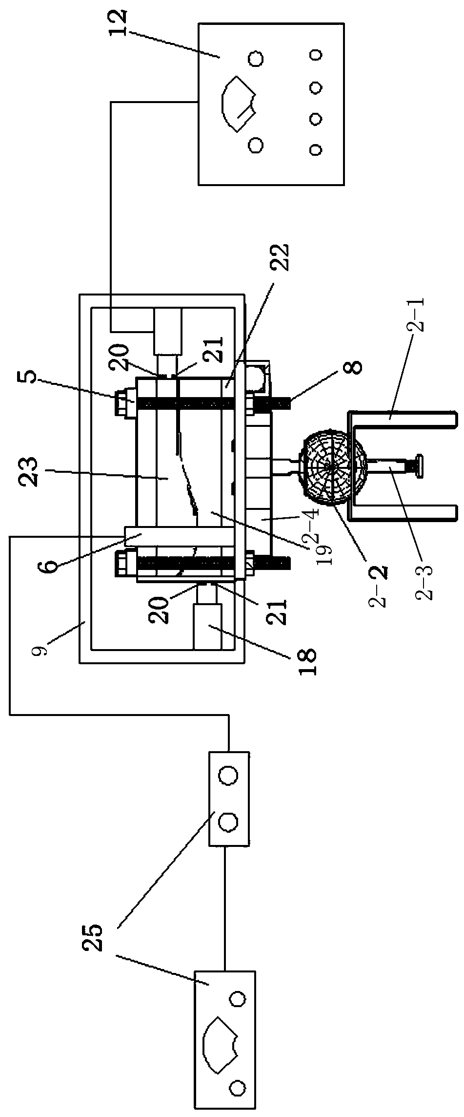
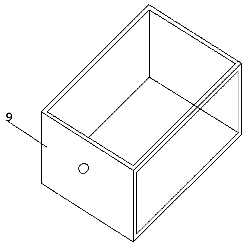
[0030] Such as Figure 1-Figure 4 As shown, a device for simulating and visualizing fissure seepage by using magnetic fluid includes a main frame 1, on which a telescopic support rod is arranged, and a movable sub-frame 10 is slidably connected to the top surface of the main frame 1, and is installed on the main frame 1 The camera 7 inside is connected to the movable sub-frame 10 through the top universal ball joint 11 on the main frame 1, and the shearing reaction frame 9 is installed on the bottom plate 1-1 of the main frame 1 through the universal ball joint reaction device 2 On the surface, the visualized rock sample 26 is placed on the upper surface of the shear reaction force frame 9 through the expansion pressurized air cushion 22, and the expanded pressurized air cushion 22 communicates with the inflatable device 24. Composition, a crack is formed between the transparent resin 23 of the upper cover plate and the common rock sample 19, and the two sides of the visualize...

Embodiment 2

[0037] A method for simulating and visualizing fracture seepage using the above-mentioned device, the method includes the following steps:

[0038] Step 1: Adjust the angle of the top universal ball joint 11 so that the camera 7 is perpendicular to the top surface of the visualized rock sample 26;

[0039] Step 2: Adjust the height of the telescopic support rod, and place the camera 7 in a suitable position (it can clearly capture the visual seepage situation without reflections, ghosting, etc. that affect the later experimental data processing);

[0040]Step 3: Inject gas into the expansion pressurized air cushion 22 through the inflation device 24 (use the pressure gauge on the high-pressure nitrogen cylinder to adjust the pressure), and adjust the normal stress on the visualized rock sample 26;

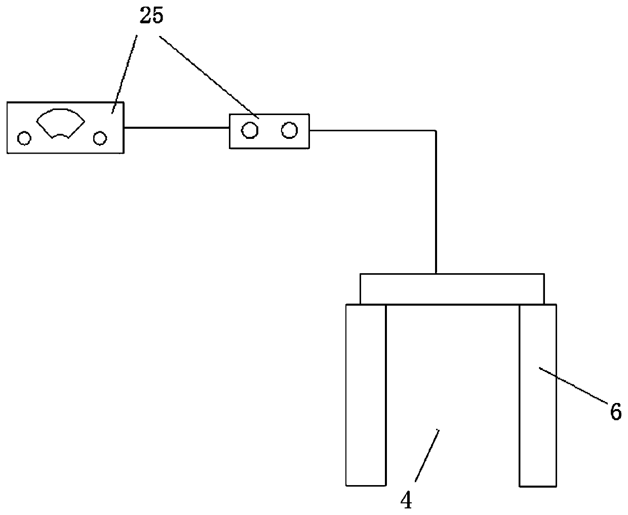
[0041] Step 4: Turn on the shearing loading device 18, and control the magnitude of the shearing force by adjusting the thrust of the hydraulic rod. The magnitude of the shearing f...

Embodiment 3

[0045] In the first embodiment above, the preparation method of the visualized rock sample 26 is as follows:

[0046] Step a: Prepare the rock split surface: collect rocks with natural joints and fissures (including opposite surfaces) or split a block of rock to obtain a split surface, the size of which depends on the test requirements;

[0047] Step b: prepare test silica gel according to the mass ratio of hardener and liquid silica gel at 1:50, pour liquid silica gel evenly on the cracked surface of the rock sample to be simulated, wait for it to solidify and harden after 3 hours, and take it out Down;

[0048] Step c: Preparation of transparent resin: take a certain amount of liquid resin in a suitable container, first add accelerator with mass content of 0.6%-0.8% and stir for 2 minutes, then add accelerator with mass content of 0.6%-0.8% Hardener, stir for 2 minutes, finally add defoamer with a mass content of 0.6%-1.2%, stir slowly for 2 minutes, the whole process shoul...


PUM

PropertyMeasurementUnit
thicknessaaaaaaaaaa

Abstract

A device for simulating visual gap seepage by magnetic fluid comprises a main body framework, wherein a camera is arranged in the main body framework and is hinged with a mobile auxiliary framework bya top universal ball on the main body framework, a visual rock sample is placed on an upper surface of a shearing counter-force rack by an expansion pressurization pad and comprises upper cover platetransparent resin and a conventional rock sample, a gap is formed between the upper cover plate transparent resin and the conventional rock sample, two side surfaces of the visual rock sample are connected with an inner side wall of the shearing counter-force rack by a hydraulic rod loading device, a stress sensor and a displacement sensor are arranged at the hydraulic rod loading device, and a paste/water injection pipe of a paste/water injection device is matched with the gap between the upper cover plate transparent resin and the conventional rock sample. With the device and method for simulating visual gap seepage by magnetic fluid, provided by the invention, the seepage rules under various conditions are researched by the magnetic fluid to simulate gap seepage conditions under conditions of multi-angle different confining pressure and yawing forces.

Description

technical field [0001] The invention relates to the technical field of rock fissure testing, in particular to a device and method for simulating and visualizing fissure seepage using magnetic fluid. Background technique [0002] In recent years, with the continuous development of domestic infrastructure projects, the construction scale of various tunnels (caves) has also continued to expand. my country has become the country with the largest construction scale and the most stringent quality requirements in the world. In geotechnical engineering such as mining, water conservancy and hydropower, tunnels, and slope reinforcement, joint fissures have an important impact on the stability of rock mass engineering. On the one hand, cracks in rock mass are one of the important causes of water damage in underground engineering. On the other hand, the existence of cracks also greatly reduces the strength of rock mass. Filling the cracks by grouting can not only effectively prevent wa...

Claims


Application Information

Patent Timeline
Patent Type & Authority Applications(China)
IPC IPC(8): G01N15/08
CPCG01N15/0806G01N15/082G01N15/08G01N2015/0846
Inventor 刘杰黎照张子睿王舒羽高素芳孙涛唐洪宇石谦李政蔡显灿沈豪炜李远航何卓文吴子进巫江洪赵敏吴浩
Owner CHINA THREE GORGES UNIV
Why Eureka
Try Eureka