A radio frequency channel calibration method and device

A technology of radio frequency channel and calibration method, applied in transmitter monitoring, receiver monitoring, transmission monitoring and other directions, can solve the problems of poor test repeatability, poor test controllability, unable to guarantee the channel consistency of amplitude and phase, etc. Consistency, the effect of ensuring test reliability

Active Publication Date: 2022-05-06
ZTE CORP
View PDF6 Cites 0 Cited by
  • Summary
  • Abstract
  • Description
  • Claims
  • Application Information

AI Technical Summary

Problems solved by technology

Usually, the test is carried out in a real wireless field, but the controllability of this test is relatively poor, the test results are easily disturbed by the external field, and the test repeatability is poor, which will lead to the unstandardization of the entire test
[0003] At present, many test instrument manufacturers also intend to use software algorithms to simulate the space separation scenario of multi-user terminals (UE, UserEquipment). This method will face a problem, namely: the radio frequency channel of the device under test and the radio frequency channel of the test instrument They are all calibrated individually. Once the device under test and the test instrument are connected through an RF cable, the channel consistency of the amplitude and phase cannot be guaranteed to a certain extent.

Method used


Image

  • A radio frequency channel calibration method and device
  • A radio frequency channel calibration method and device
  • A radio frequency channel calibration method and device

Examples


Embodiment Construction

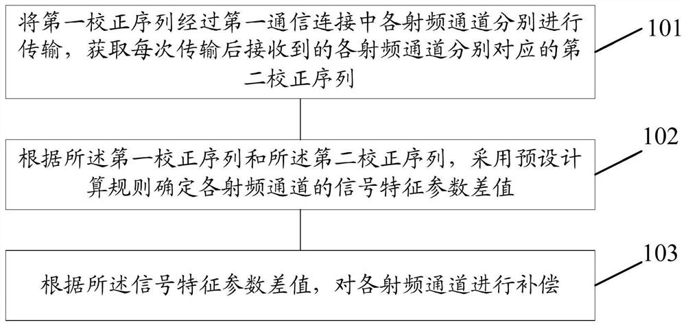
[0058] In the embodiment of the present invention, the first calibration sequence is transmitted through each radio frequency channel in the first communication connection, respectively, and the second calibration sequence corresponding to each radio frequency channel received after each transmission is obtained; according to the first calibration sequence and the second correction sequence, using a preset calculation rule to determine the difference value of the signal characteristic parameter of each radio frequency channel; according to the difference value of the signal characteristic parameter, each radio frequency channel is compensated.

[0059] The radio frequency channel correction method provided by the embodiment of the present invention, such as figure 1 As shown, the method includes:

[0060] Step 101 : respectively transmitting the first calibration sequence through each radio frequency channel in the first communication connection, and acquiring the second calibra...


PUM


Abstract

The embodiment of the present invention discloses a radio frequency channel calibration method. The first calibration sequence is respectively transmitted through each radio frequency channel in the first communication connection, and the second calibration sequence corresponding to each radio frequency channel received after each transmission is obtained; according to the first calibration sequence and the second calibration sequence sequence, using a preset calculation rule to determine the difference value of the signal characteristic parameter of each radio frequency channel; according to the difference value of the signal characteristic parameter, each radio frequency channel is compensated. The embodiment of the present invention also discloses a radio frequency channel correction device, a storage medium and an information processing device.

Description

technical field [0001] The present invention relates to digital communication technology, in particular to a radio frequency channel calibration method and device. Background technique [0002] The Long Term Evolution (LTE, Long Term Evolution) network of the fourth generation (4G, 4th Generation) mobile communication introduces the concept of service beams, and the pre-fifth generation (Pre5G, Pre 5th Generation) and fifth generation (5G, 5th Generation) mobile communication wireless The network has introduced large-scale antenna array technology, Massive MIMO (Multiple-Input Multiple-Output) and Beamforming (beamforming) technologies have become mainstream, and multi-service beam space division has become the norm, but how to perform multi-user space division Testing becomes the problem. Usually, the test is carried out in a real wireless field, but the controllability of this test is relatively poor, the test results are easily disturbed by the external field, and the te...

Claims


Application Information

Patent Timeline
Patent Type & Authority Patents(China)
IPC IPC(8): H04B17/11H04B17/10H04B17/12H04B17/21H04B17/309H04B1/12
CPCH04B17/11H04B17/101H04B17/12H04B17/21H04B17/309H04B1/12
Inventor 颜林江陈子福
Owner ZTE CORP
Why Eureka
Try Eureka