Automatic rotating conveying module

A module and camera module technology, applied in the direction of conveyors, conveyor objects, cleaning devices, etc., can solve problems such as low precision, large measurement errors, and affecting detection results, achieving strong versatility and avoiding the impact of cleanliness Effect

Inactive Publication Date: 2019-10-08
BOZHON PRECISION IND TECH CO LTD
View PDF4 Cites 2 Cited by
  • Summary
  • Abstract
  • Description
  • Claims
  • Application Information

AI Technical Summary

Problems solved by technology

There are two deficiencies in the direct reading measurement method: first, the measurement error is large and the accuracy is low
[0003] In the prior art, the utility model patent with the publication number CN207600969U discloses a cylindrical battery appearance detection device, which uses a roller set to drive the battery to rotate when detecting the circumference of the battery. The method of force rotation is obviously easy to produce errors due to slipping, which affects the detection effect, especially after the rubber wheel is aged and worn, the friction force is greatly reduced, and the roller cannot be used and must be replaced, which brings a lot of inconvenience

Method used


Image

  • Automatic rotating conveying module
  • Automatic rotating conveying module
  • Automatic rotating conveying module

Examples


Embodiment

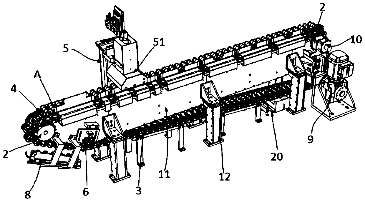
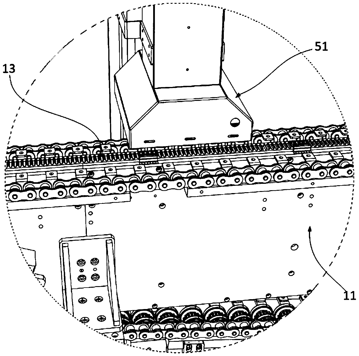
[0062] This embodiment provides an autotransformable transfer module, such as Figure 1-4 shown, including:

[0063] A frame, which includes a strip-shaped frame body 11 and support legs 12 fixed on both sides of the body 11;

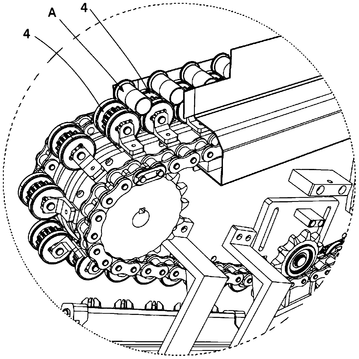
[0064] The sprockets 2 are arranged in pairs at each corner of the frame body 11 and can rotate, and each pair of sprockets 2 is divided into two that are separated from each other on both sides of the frame body 11;

[0065] The chain 3 is divided into two separated on both sides of the frame main body 11, which are sequentially connected with the sprockets 2 on both sides of the frame main body 11;

[0066] The drive device 9 is used to drive the assembly of the sprocket 2 and the chain 3 to move, and the drive device 9 is connected to one of the sprocket 2;

[0067] Several rollers 4 arranged side by side, the rollers 4 include two wheel bodies 41, gears 42, "L" shaped fixing seats 43 on both sides, and shaft cores 44, the gears 42 are fixed between ...


PUM


Abstract

The invention relates to an automatic rotating conveying module. The module comprises a machine frame, a circulating conveying device, a plurality of rolling wheels which are arranged side by side anda camera module, wherein the circulating conveying device is arranged on the machine frame, and the top surface of the circulating conveying device forms a horizontal conveying surface; the pluralityof rolling wheels which are arranged side by side are arranged on the circulating conveying device, can rotate and can move along with the circulating conveying device under the driving of the circulating conveying device; the camera module is positioned right above the horizontal conveying surface; and a rack is arranged at the position, corresponding to the horizontal conveying surface, on themachine frame, gears are arranged on the outer peripheral surfaces of the rolling wheels, when the rolling wheels are conveyed to the position where the rack is located by the circulating conveying device, the gears on the outer peripheral surfaces of the rolling wheels are matched with the rack to enable the rolling wheels to pass through the position below the camera module in a rotating mode, and the length of the rack is larger than the outer circumference of the gears. According to the module, a chain is used for conveying products, products are rotated automatically on the chains, the appearance defects of the products are detected by using a high-speed camera, the stability is high, and the misjudgment rate is low.

Description

technical field [0001] The application belongs to the technical field of detection equipment, and in particular relates to a detection equipment for circular products. Background technique [0002] In the field of modern machinery manufacturing, one of the basic features of machined mechanical parts is the circular feature. For example: ferrules, cylinders, spheres, etc., are all mechanical parts with circular features. Circular parts are widely used in many fields. The automatic and accurate measurement of their geometric dimensions can not only ensure the processing quality of parts, but also play a key role in improving production efficiency. The size inspection of circular parts is one of the important contents of mechanical production inspection. The traditional measurement method is to directly measure the part to be measured with the measuring tool, and obtain the geometric dimension of the part to be measured through reading. The measuring tools used mainly includ...

Claims


Application Information

Patent Timeline
Patent Type & Authority Applications(China)
IPC IPC(8): B65G23/44B65G23/24B65G45/10B65G23/06B65G17/38
CPCB65G17/38B65G23/06B65G23/24B65G23/44B65G45/10
Inventor 洪豪杰
Owner BOZHON PRECISION IND TECH CO LTD
Why Eureka
Try Eureka