Hydraulic impactor driven by spiral impeller

A technology of hydraulic impactor and helical impeller, which is applied in the field of oil drilling, can solve the problems of short life of impactor and small single impact force, and achieve the effects of stable working performance, large impact force, and easy use and promotion.

Inactive Publication Date: 2019-10-08
CNPC BOHAI DRILLING ENG
View PDF5 Cites 5 Cited by
  • Summary
  • Abstract
  • Description
  • Claims
  • Application Information

AI Technical Summary

Problems solved by technology

[0005] The purpose of the present invention is to overcome the deficiencies of the prior art, and provide a hydraulic impactor driven by a spiral impeller for solving the problems of the existing impactor such as too short life span and too small single impact force

Method used


Image

  • Hydraulic impactor driven by spiral impeller
  • Hydraulic impactor driven by spiral impeller
  • Hydraulic impactor driven by spiral impeller

Examples


Embodiment 1

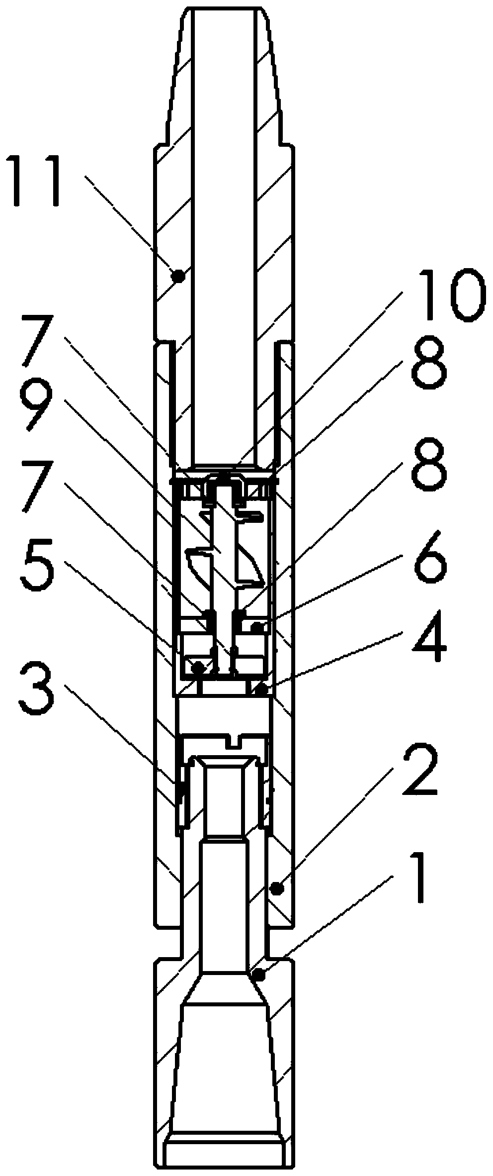
[0052] Such as Figure 1-16 As shown, a hydraulic impactor driven by a helical impeller provided in this embodiment includes a transmission short 1, a screw lock 3, an impact chamber 2, a rectifier 4, an impeller shaft 9, and an impactor main body 11;

[0053] The rectifier 4 is a hollow cylindrical structure, and one end of the rectifier 4 is open, and the other end is provided with a closed plate 401, and the closed plate 401 is provided with a through discharge hole 402 and a main channel 403; the impeller shaft 9 An impeller 901 is arranged on it, and an upper fixed plate 10 and a lower fixed plate 6 are respectively arranged on the impeller shaft 9 above and below the impeller 901. The end of the impeller shaft 9 is provided with a transmission plate 5, and the upper fixed plate 10 and the lower fixed plate 6 are provided with a flow port 12, and the transmission plate 5 is provided with a flow hole 501; the impeller shaft 9 is located in the rectifier 4, and the transmis...


PUM


Abstract

The invention relates to a hydraulic impactor driven by a spiral impeller. The hydraulic impactor driven by the spiral impeller comprises a transmission pup joint, a threaded lock, an impact cavity, arectifier, an impeller shaft and an impactor main body; one end of the rectifier is open and the other end of the rectifier is provided with a closed plate; the closed plate is provided with run-through drainage hole and main flow channel; an impeller is arranged on the impeller shaft; an upper fixed plate and a lower fixed plate are arranged on the impeller shaft positioned above and below the impeller correspondingly; a transmission plate is arranged at the tail end of the impeller shaft; the upper fixed plate and the lower fixed plate are provided with flow channel mouths correspondingly;the transmission plate is provided with an overflow hole; the impeller shaft is positioned in the rectifier; the transmission plate is positioned on one side of the closed plate and positioned above the closed plate; the impact cavity adopts a hollow run-through structure; the top of the impact cavity is in threaded connection with the impactor main body; the threaded lock is positioned blow the internal part of the impact cavity; one end of the transmission pup joint is inserted into the impact cavity and is in threaded connection with the threaded lock; and the transmission pup joint and theimpact cavity are matched through an orthohexagnal surface. The hydraulic impactor driven by the spiral impeller can solve the problems that the existing impactor has too short life and too small single-time impact force.

Description

technical field [0001] The invention belongs to the technical field of petroleum drilling, in particular to a hydraulic impactor driven by a helical impeller. Background technique [0002] As the depth of the mining strata increases, the mining strata become more and more complex, and the difficulty of development increases, especially for the mining of deep wells and ultra-deep wells. The damage to the drill bit increases, the footage speed is slow, and the problems of high drilling cost become more and more prominent. Therefore, improving drilling efficiency and reducing drilling costs are key issues that need to be solved urgently in the oil drilling industry at home and abroad. [0003] At present, various impactors are the main drilling tools for increasing the drilling speed. The hydraulic impactor can effectively increase the unit footage time of the PDC bit, and because the hydraulic impactor that can form pulsed jet has cavitation effect, it can greatly improve th...

Claims


Application Information

Patent Timeline
Patent Type & Authority Applications(China)
IPC IPC(8): E21B7/18
CPCE21B7/18
Inventor 周俊然陈世春杨冀平王益山董颖董赵朋田晓勇
Owner CNPC BOHAI DRILLING ENG
Why Eureka
Try Eureka