Continuous injection vacuum chamber

A vacuum chamber and sampling port technology, applied in the field of vacuum chambers, can solve problems such as inability to continuously inject samples, poor reliability, and leakage

Pending Publication Date: 2019-10-08
ZHEJIANG DIGENA DIAGNOSTIC TECH CO LTD
View PDF0 Cites 0 Cited by
  • Summary
  • Abstract
  • Description
  • Claims
  • Application Information

AI Technical Summary

Problems solved by technology

[0002] Mass spectrometry is a detection technology with very high accuracy and reliability. Mass spectrometry needs to test the time of flight of ions in a vacuum environment. The current solution is generally to send the sample into the vacuum chamber, which cannot continuously inject samples. When replacing the sample When the vacuum in the vacuum chamber is leaked, it needs to be re-evacuated. After the sample is injected, it needs to wait for the vacuum to be re-established. It takes tens of minutes or several hours. short

Method used


Image

  • Continuous injection vacuum chamber
  • Continuous injection vacuum chamber
  • Continuous injection vacuum chamber

Examples


Embodiment 1

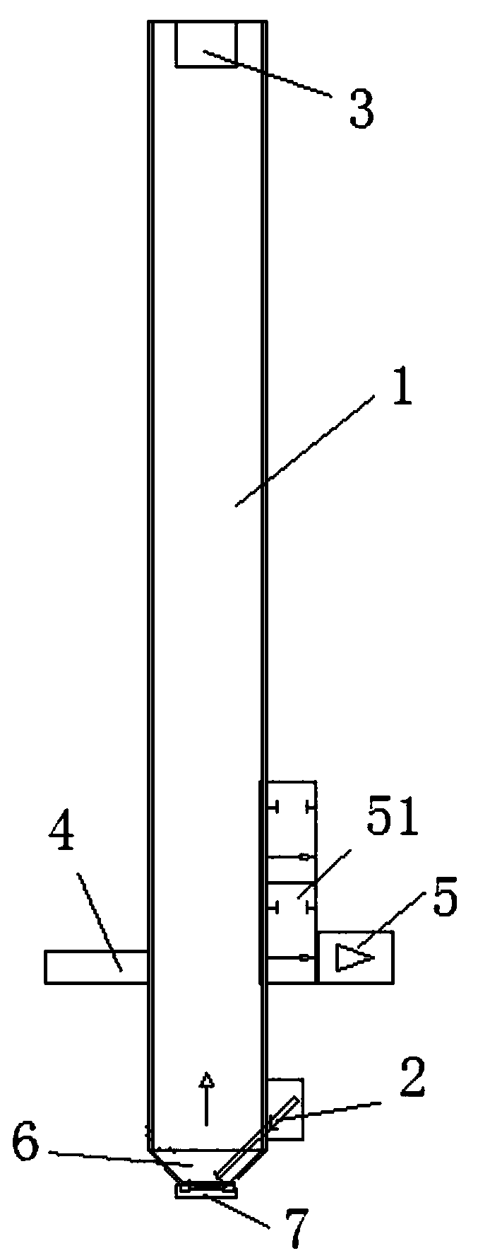
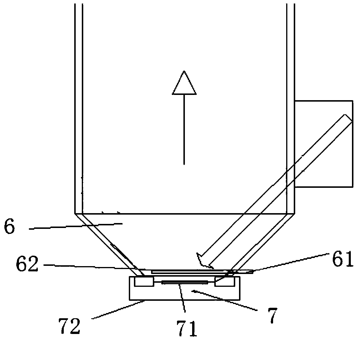
[0026] Such as Figure 1-3 Shown, a continuous sampling vacuum chamber, including

[0027] A vacuum chamber 1, the vacuum chamber 1 is provided with an ion exciter 2 and an ion detector 3. The vacuum chamber is a circular cavity with a length of 0.3M to 2M (the circular cavity is only a preferred method), and the top of the cavity is Closed, the bottom of the cavity is open, the ion exciter 2 is set at the bottom of the vacuum chamber, the ion detector 3 is set at the top of the vacuum chamber, the cavity is formed as an ion flight channel, the ion exciter is introduced from the non-axis of the vacuum chamber, and the introduction angle is 10°~170°;

[0028] A vacuum gauge 4, the vacuum gauge 4 communicates with the vacuum chamber 1;

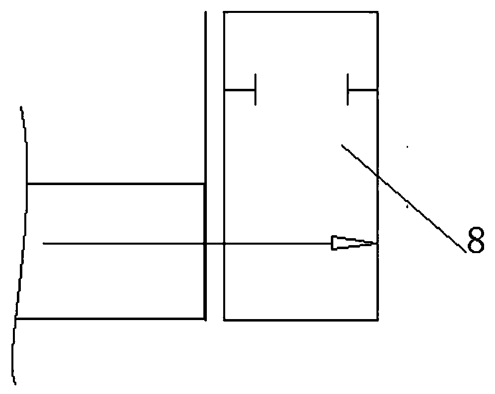
[0029] Vacuum pump 5, described vacuum pump 5 is connected with vacuum chamber 1 by vacuum valve 51, and vacuum chamber is disconnected with vacuum pump when closing vacuum valve, and vacuum degree is better than 10 6 mBar;

[0030] The samp...


PUM


Abstract

The invention discloses a continuous injection vacuum chamber. The continuous injection vacuum chamber includes a vacuum chamber provided with an ion exciter and an ion detector, a vacuum gauge communicated with the vacuum chamber, and a vacuum pump. The continuous injection vacuum chamber is advantaged in that continuous injection can be achieved, work efficiency is improved, and service life isimproved.

Description

Technical field: [0001] The invention relates to a vacuum chamber in the field of biological mass spectrometry detection, in particular to a vacuum chamber with good sealing performance, fast vacuum establishment and maintenance speed, continuous sampling and continuous detection. Background technique: [0002] Mass spectrometry is a detection technology with very high accuracy and reliability. Mass spectrometry needs to test the time of flight of ions in a vacuum environment. The current solution is generally to send the sample into the vacuum chamber, which cannot continuously inject samples. When replacing the sample When the vacuum in the vacuum chamber is leaked, it needs to be re-evacuated. After the sample is injected, it needs to wait for the vacuum to be re-established. It takes tens of minutes or several hours. short. Invention content: [0003] The technical problem to be solved by the present invention is to provide a continuous sampling vacuum chamber capable...

Claims


Application Information

Patent Timeline
Patent Type & Authority Applications(China)
IPC IPC(8): H01J49/04G01N27/62
CPCH01J49/0495H01J49/0409G01N27/62
Inventor 相双红张郁
Owner ZHEJIANG DIGENA DIAGNOSTIC TECH CO LTD
Why Eureka
Try Eureka