Evaporative vacuum drainer
A drainer and vacuum technology, applied in the field of evaporative vacuum drainers, can solve the problems of not very suitable, no automatic control system, etc.
- Summary
- Abstract
- Description
- Claims
- Application Information
AI Technical Summary
Problems solved by technology
Method used
Image
Examples
Embodiment Construction
[0018] The present invention will be further described below with regard to specific embodiments.
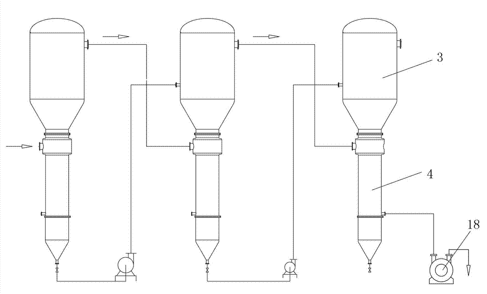
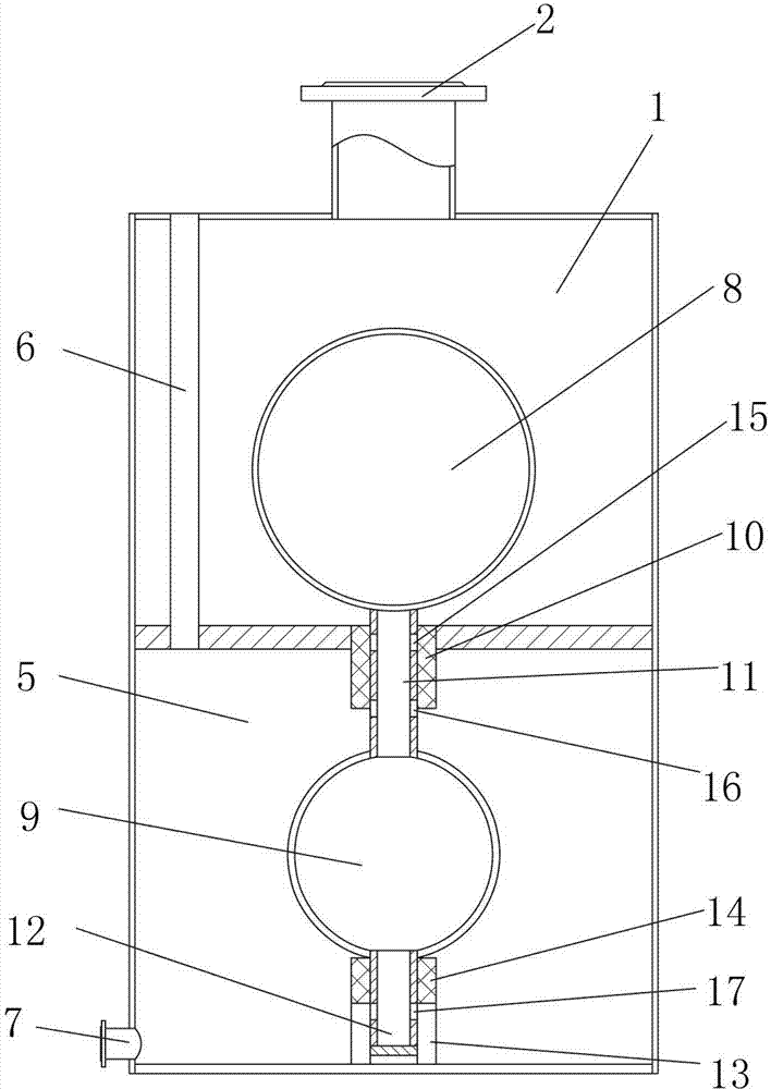
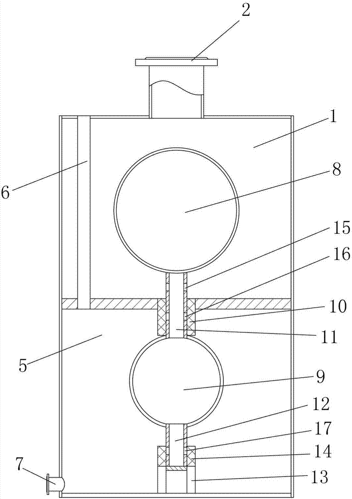
[0019] according to Figure 2-Figure 5 , the present invention comprises a vacuum chamber 1, a balance chamber 5, a hollow floating device mainly composed of an upper float 8, a lower float 9, a sliding pipe 11, and a drainage pipe 12, a vacuum valve group, and a balance valve group.
[0020] The vacuum valve group is composed of a water hole a15 and a hole valve switch. The water hole a15 is located on the sliding pipe 11 at the connection between the sliding pipe 11 and the upper floating ball 8. The a hole valve switch is located outside the water hole a15 or on the On or formed by the sealed channel 10, the sealed channel 10 is used as the a hole valve switch of the water hole a15 in the figure.
[0021] The balance valve group is composed of water hole b16, water hole c17, b-hole valve switch, and c-hole valve switch. Below a15; the water hole c17 is located on the draina...
PUM
 Abstract
Description
Claims
Application Information
 - R&D
- Intellectual Property
- Life Sciences
- Materials
- Tech Scout
- Unparalleled Data Quality
- Higher Quality Content
- 60% Fewer Hallucinations
Browse by: Latest US Patents, China's latest patents, Technical Efficacy Thesaurus, Application Domain, Technology Topic, Popular Technical Reports.
© 2025 PatSnap. All rights reserved.Legal|Privacy policy|Modern Slavery Act Transparency Statement|Sitemap|About US| Contact US: help@patsnap.com


