High-light-transmittance protection device for camera production and application thereof

A protection device, high light transmittance technology, applied in image communication, TV, color TV parts and other directions, can solve the problems of low injection molding efficiency, high defect ratio, low production efficiency, etc., to increase the market. The effect of competitiveness, labor cost reduction, and manufacturing cost reduction

Pending Publication Date: 2019-10-08
深圳市利和腾鑫科技有限公司
View PDF0 Cites 0 Cited by
  • Summary
  • Abstract
  • Description
  • Claims
  • Application Information

AI Technical Summary

Problems solved by technology

The structure of foam + high-permeability film generally requires die-cutting processing. Due to the influence of material characteristics and product structure, the entire processing process has more strokes, low production efficiency, and a high proportion of defects; while injection molding sleeve + high-permeability film or optical The glass structure and the injection molding sleeve can be formed at one time through injection molding, but the high-permeability film and the adhesive need to be die-cut, and the process of assembling the injection molding sleeve is not very efficient; and the optical glass sealing film, due to its special material, has high processing costs and low assembly efficiency. Low, high proportion of non-performing

Method used


Image

  • High-light-transmittance protection device for camera production and application thereof
  • High-light-transmittance protection device for camera production and application thereof
  • High-light-transmittance protection device for camera production and application thereof

Examples


Embodiment Construction

[0022] The following will clearly and completely describe the technical solutions in the embodiments of the present invention with reference to the accompanying drawings in the embodiments of the present invention. Obviously, the described embodiments are only some, not all, embodiments of the present invention. Based on the embodiments of the present invention, all other embodiments obtained by persons of ordinary skill in the art without making creative efforts belong to the protection scope of the present invention.

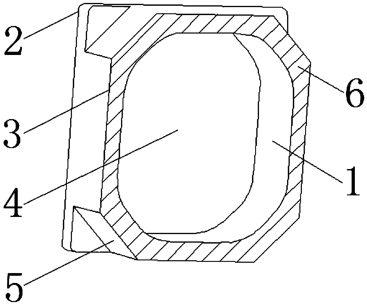
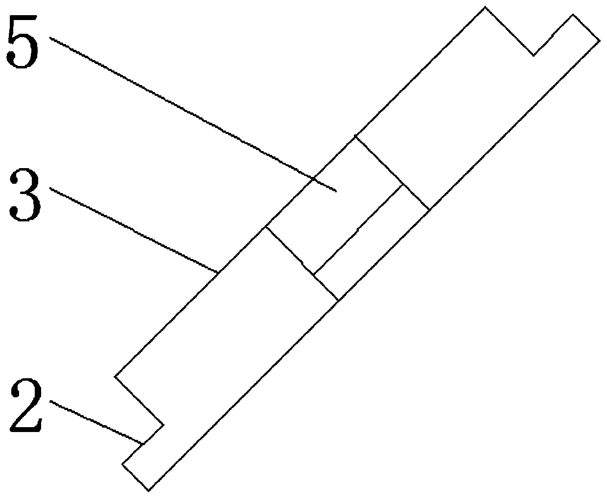
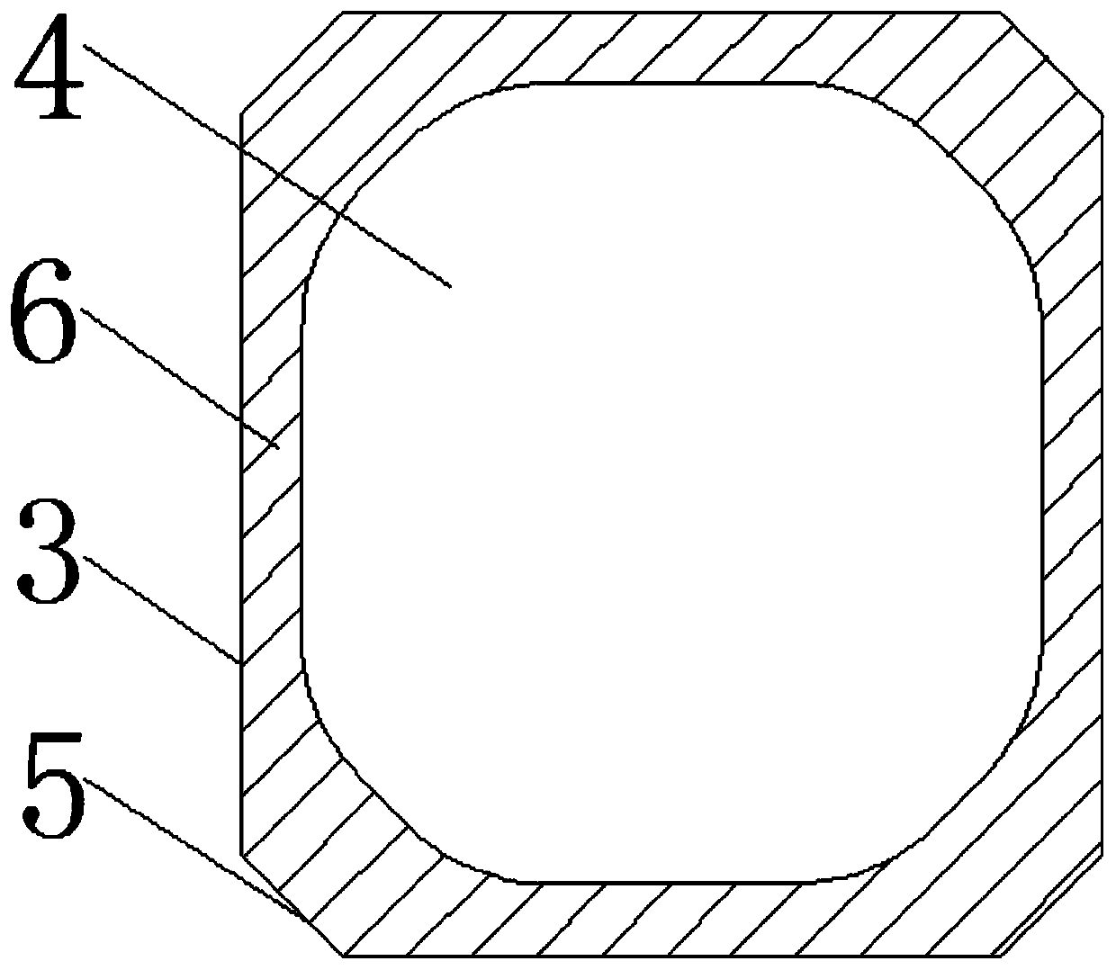
[0023] see Figure 1-5 , in an embodiment of the present invention, a high light transmittance protective device for camera production, including a protective device body 1, a high light transmittance cover film 2, a protective sleeve body 3 and a protective cavity 4, the protective device body 1 is composed of a high light transmittance The cover film 2 and the protective cover body 3 are composed. The high-transmittance cover film 2 is arranged on the top of...


PUM


Abstract

The invention discloses a high-light-transmittance protection device for camera production and an application thereof. The device comprises a protection device body, a high-light-transmittance cover film, a protection sleeve body and a protection cavity. The protection device body is composed of the high-light-transmittance cover film and the protection sleeve body, the high-light-transmittance cover film is arranged on the top of the protection sleeve body, and the protection sleeve body is integrally formed through an injection molding technology. A protective cavity is formed in the protective sleeve body, the protective sleeve body is of a structure with one side open and three sides closed, double-sided adhesive tape is bonded to one side open of the protective sleeve body, an AR coating film is arranged on the outer side of the other side corresponding to the opening, and the opening of the protective sleeve body is used for loading and protecting a camera, and a high-light-transmission cover film corresponds to the position of a camera lens. The mold of the protection device body is designed, the optical material is used for injection molding, the protection sleeve body is integrally formed through injection molding, the high-light-transmission requirement of a client is met, meanwhile, the technological structure is improved, the labor cost is reduced, the manufacturingcost is reduced, the total yield is improved, the comprehensive benefits are improved, and the market competitiveness of products is improved.

Description

technical field [0001] The invention relates to a camera protection device, in particular to a high light transmittance protection device for camera production, which is mainly used in the protection of the camera production process of smart phones, tablet computers, notebook computers, PCs and other equipment. Background technique [0002] Since Sharp was the first to apply cameras to mobile phones in 2000, cameras have become more and more important in mobile phones. From simply taking pictures at the beginning to now recording the world, biometrics, AI applications and other human-computer interactions, the role of cameras has become more and more extensive; the number has also been single-camera, and now it has become dual-camera, triple-camera and even quadruple-camera. As mobile phone cameras are optical devices and are small in size, if they are not strictly protected during the process of manufacturing, transportation, testing, and installation, they will easily be d...

Claims


Application Information

Patent Timeline
IPC IPC(8): H04N5/225
CPCH04N23/51
Inventor 王光平方兆山吕启超
Owner 深圳市利和腾鑫科技有限公司
Why Eureka
Try Eureka