Turnover device for steel structure welding

A turning device and steel structure technology, applied in the field of steel structure, can solve the problems affecting the efficiency of automatic welding, increase the labor intensity and risk factor of workers, etc., and achieve the effect of reasonable and low structure cost, stable and firm fixed structure, and ingenious structure design

Inactive Publication Date: 2019-10-11
HUBEI XINSUO CONSTR
View PDF0 Cites 2 Cited by
  • Summary
  • Abstract
  • Description
  • Claims
  • Application Information

AI Technical Summary

Problems solved by technology

[0002] Welding is mainly to heat the metals to be welded by using electricity to melt and fuse them. It is an important processing method for the connection between metals in metal processing. In the welding of steel structures, the traditional welding method is mainly through manual welding. Welding, but with the progress of science and the development of science and technology, automatic welding gradually replaces manual work. The weld seam of some steel structure weldments is not a straight line, so it needs to be turned over during automatic welding. Traditional manual turning not only affects Improve the efficiency of automatic welding, and increase the labor intensity and risk factor of workers

Method used


Image

  • Turnover device for steel structure welding
  • Turnover device for steel structure welding
  • Turnover device for steel structure welding

Examples


Embodiment Construction

[0014] The following will clearly and completely describe the technical solutions in the embodiments of the present invention with reference to the accompanying drawings in the embodiments of the present invention. Obviously, the described embodiments are only some, not all, embodiments of the present invention.

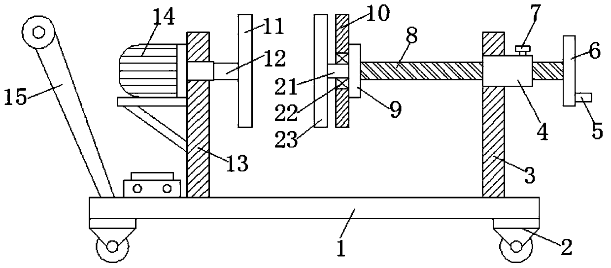
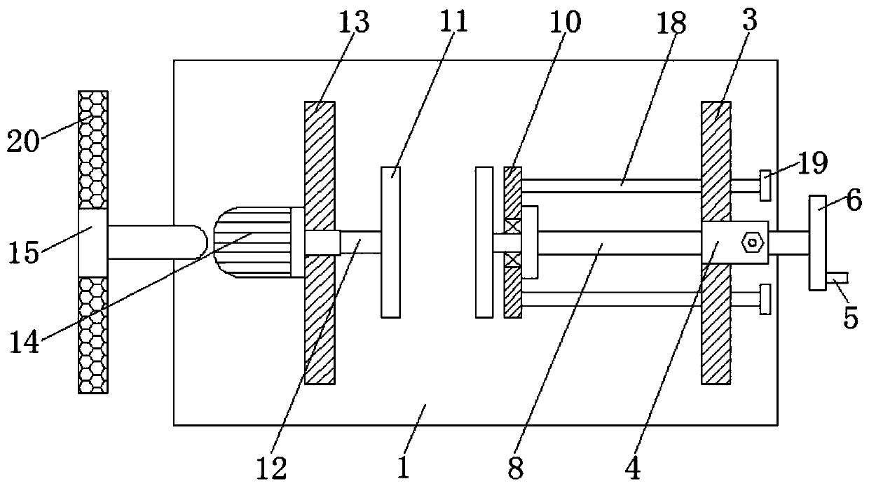
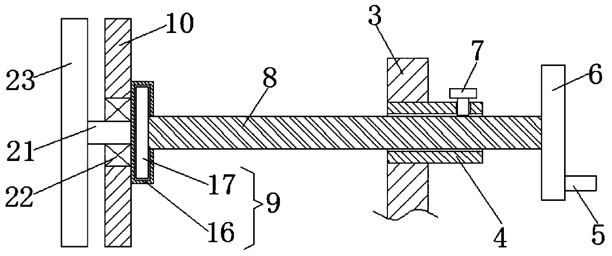
[0015] refer to Figure 1-3 , a turning device for steel structure welding, including a base plate 1, wheels 2 are fixedly installed at the four corners of the bottom surface of the base plate 1, and the wheels 2 are specifically rubber wheels with foot brakes, and the movement of the device is facilitated by the wheels 2 And use, and by foot brake, can fix this device, has avoided its moving when not needed.

[0016] A first support plate 3 is fixedly installed on one side of the upper surface of the base plate 1, a second support plate 13 is fixedly installed on the other side of the upper surface of the base plate 1, a motor 14 is fixedly installed on the upper pa...


PUM


Abstract

The invention relates to the technical field of steel structures, in particular to a turnover device for steel structure welding. The device comprises a bottom plate, a first supporting plate is fixedly arranged on one side of the upper surface of the bottom plate, one end of an output shaft of a motor penetrates through a second supporting plate and is fixedly provided with a rotating shaft, oneend of the rotating shaft is fixedly provided with a second fixing plate, a threaded sleeve pipe is fixedly arranged at the upper part of the first supporting plate in a penetrating mode, the threadedsleeve pipe is in threaded connection with a threaded rod, one side of the rotating mechanism is fixedly provided with a first fixing plate, guiding rods are fixedly arranged at the two ends of one side of the first fixing plate, the other end of the threaded rod extends to the other side of the threaded sleeve pipe and is fixedly provided with a rotating disc, a rotating handle is fixedly arranged on one side of the rotating disc, a fastening nut is fixedly arranged on one side of the upper surface of the threaded sleeve pipe, and a pushing rod is fixedly arranged on one side of the upper surface of the bottom plate. The turnover device for steel structure welding has the advantages of being used for conveniently fixing and turning over steel structure welded parts, and being simple to operate, convenient to use and high in practicability.

Description

technical field [0001] The invention relates to the technical field of steel structures, in particular to a turning device for steel structure welding. Background technique [0002] Welding is mainly to heat the metals to be welded by using electricity to melt and fuse them. It is an important processing method for the connection between metals in metal processing. In the welding of steel structures, the traditional welding method is mainly through manual welding. Welding, but with the progress of science and the development of science and technology, automatic welding gradually replaces manual work. The weld seam of some steel structure weldments is not a straight line, so it needs to be turned over during automatic welding. Traditional manual turning not only affects It not only improves the efficiency of automatic welding, but also increases the labor intensity and risk factor of workers. Therefore, for the above-mentioned problems, it needs to be improved. Contents of...

Claims


Application Information

Patent Timeline
Patent Type & Authority Applications(China)
IPC IPC(8): B23K37/047
CPCB23K37/047
Inventor 李亮李超群
Owner HUBEI XINSUO CONSTR
Why Eureka
Try Eureka