Embedded accompanying tool bridge for automobile aluminum alloy frame

An aluminum alloy and built-in technology, which is applied in metal processing, metal processing equipment, manufacturing tools, etc., can solve the problems that cannot be recycled repeatedly, destroy the structure of the beam body, and the fixture cannot follow, etc., to achieve light weight, small size, compact effect

Active Publication Date: 2019-10-11
NANNING HUASHU LIGHTWEIGHT ELECTRIC VEHICLE DESIGN INST CO LTD +1
View PDF18 Cites 0 Cited by
  • Summary
  • Abstract
  • Description
  • Claims
  • Application Information

AI Technical Summary

Problems solved by technology

The above-mentioned patent fixes the car frame by cooperating with the positioning holes, positioning posts, limit posts and the corresponding holes on the car frame. It is necessary to set a positioning hole on the frame to cooperate with the clamping of the car frame, which destroys the body structure of the frame. Moreover, the fixture cannot follow the assembly line of the automobile frame, the operation is cumbersome and complicated, and there are many components, so it cannot be recycled repeatedly

Method used


Image

  • Embedded accompanying tool bridge for automobile aluminum alloy frame
  • Embedded accompanying tool bridge for automobile aluminum alloy frame
  • Embedded accompanying tool bridge for automobile aluminum alloy frame

Examples


Embodiment 1

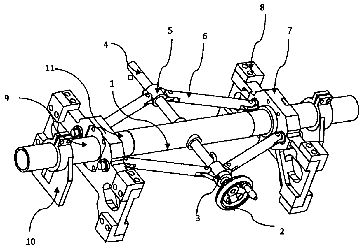
[0027] like figure 1 Shown is the basic structure of an embodiment, including a main frame 1, an outer limit plate 10, and a screw clamping and positioning mechanism. The screw clamping and positioning mechanism includes a screw 4, a connecting rod 6 and a movable base plate 7, The screw mandrel 4 passes through the through hole arranged in the middle of the main frame 1, and is vertically installed in the main frame 1. The screw rod 4 is respectively set with a screw nut hinge seat 5 on both sides of the main frame 1. The two sides of the nut hinge seat 5 are respectively hinged connecting rods 6, the movable base plate 7 is set on the main frame 1 and is slidably connected with the main frame 1, and the other end of the connecting rod 6 is hinged with the movable base plate 7, The outer limiting plate 10 is fixedly fitted on both ends of the main frame 1 and installed on the outside of the movable base plate 7 .

[0028] Optimizing on the basis of the above-mentioned embodi...

Embodiment 2

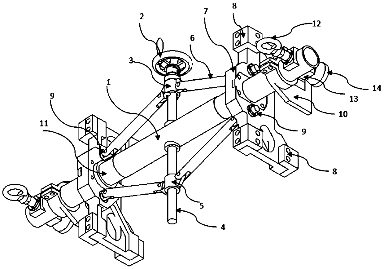
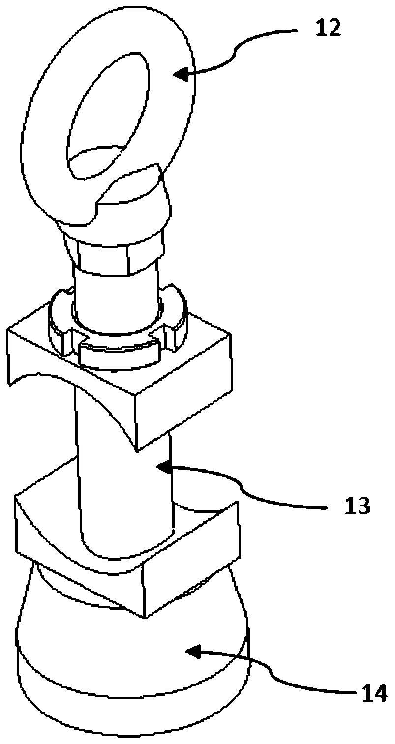
[0035] Example 2 is a further optimized solution based on Example 1. The difference between the technical solution provided by Example 2 and Example 1 is that on the basis of Example 1, the end of the main frame 1 is fixed to two Secondary positioning devices, such as figure 2 and image 3 As shown, the secondary positioning device includes an eye screw 12 at the top, a connecting rod 13 in the middle and a conical head cap 14 at the bottom. The connecting rod 13 penetrates through the main frame 1 and is fixedly connected with the main frame 1. 12 is threadedly connected with the connecting rod 13 and installed above the main frame 1, the conical plug cap 14 is fixed on the lower end of the connecting rod 13, the inside of the conical plug cap 14 is a tapered hole, the The conical plug cap 14 can be assembled and fixed with the conical plug.

[0036] The specific working process is: the figure shows the clamping and positioning mechanism of the screw rod, adjust the outer ...


PUM


Abstract

The invention discloses an embedded accompanying tool bridge for an automobile aluminum alloy frame. The tool bridge comprises a main framework, outer limiting plates and a screw rod clamping and positioning mechanism, wherein the screw rod clamping and positioning mechanism comprises a screw rod, a connecting rod and a movable base plate, the screw rod penetrates through a through hole formed inthe middle of the main framework, and is vertically arranged in the main framework, nut hinge bases are arranged on the positions, on the two sides of the main framework, of the screw rod in a sleevemode, the two sides of the nut hinge bases are correspondingly connected to connecting rods in a hinged mode, movable base plates are arranged on the main framework in a sleeve mode and are in slidingconnection with the main framework, the other ends of the connecting rods are hinged to the movable base plates, and the outer limiting plates are fixedly arranged at the two ends of the main framework in a sleeve mode and installed on the outer sides of the movable base plates. According to the tool bridge, in the process of assembling the automobile frame, the tool bridge goes along with an automobile frame assembling line, and the frame in the two directions can be positioned and fixed at the same time.

Description

technical field [0001] The invention relates to the technical field of automobile girder processing, in particular to an automobile aluminum alloy girder embedded accompanying tooling bridge. Background technique [0002] As the main load-bearing part of a car, the girder is the base of the car and plays a vital role in the entire body manufacturing process. Because of the special structure of the car frame, in order to ensure the precise positioning of the car frame during the vehicle assembly process, fixtures are usually used to assist. And for the automobile beam welding process, a reasonable fixture structure should also have a positioning function in the process of auxiliary clamping. A reasonable fixture structure is conducive to rationally arranging assembly line production, facilitating the balance of station time, and reducing production costs. Increase productivity. The current fixtures and fixtures of automobile beams generally use simple and temporary welding ...

Claims


Application Information

Patent Timeline
Patent Type & Authority Applications(China)
IPC IPC(8): B23P19/00
CPCB23P19/00
Inventor 宗志坚周江龙飞永谢永刚魏坤
Owner NANNING HUASHU LIGHTWEIGHT ELECTRIC VEHICLE DESIGN INST CO LTD
Why Eureka
Try Eureka