[0022] This section will describe the specific embodiments of the present invention in detail. The preferred embodiments of the present invention are shown in the drawings. The function of the drawings is to supplement the description of the text part of the manual with graphics, so that people can intuitively and vividly understand the text. Each technical feature and overall technical solution of the invention cannot be understood as a limitation on the protection scope of the present invention.
[0023] In the description of the present invention, it should be understood that the orientation description involved, such as up, down, front, back, left, right, etc., indicates the orientation or positional relationship based on the orientation or positional relationship shown in the drawings, and only In order to facilitate the description of the present invention and simplify the description, it does not indicate or imply that the pointed device or element must have a specific orientation, be configured and operate in a specific orientation, and therefore cannot be understood as a limitation to the present invention.
[0024] In the description of the present invention, several means one or more, multiple means two or more, greater than, less than, exceeding, etc. are understood to not include the number, and above, below, and within are understood to include the number. If it is described that the first and second are only used for the purpose of distinguishing technical features, and cannot be understood as indicating or implying the relative importance or implicitly specifying the number of the indicated technical features or implicitly specifying the order of the indicated technical features relationship.
[0025] In the description of the present invention, unless otherwise clearly defined, terms such as setting, installation, and connection should be understood in a broad sense, and those skilled in the art can reasonably determine the specific meaning of the above terms in the present invention in combination with the specific content of the technical solution.
[0026] The current examples of the pile foundation construction technology applying the present invention include: the general contracting project of the road improvement project of Huanshi Avenue West in Guangzhou Nansha Development Zone, the construction project of one museum and one center in Jiaoling County, and the new hospital construction project of Taishan Maternal and Child Health Hospital (Outpatient medical technology building, inpatient department, basement, energy center and outdoor engineering) and the general contracting of the survey, design and construction of Jianbang Hangxiao Prefabricated Building Industrial Park. These projects overcome the difficulties in the construction of pile foundations in karst areas and make pile foundations To achieve high-quality results, the project was completed on time, and the quality of the project was fully affirmed.
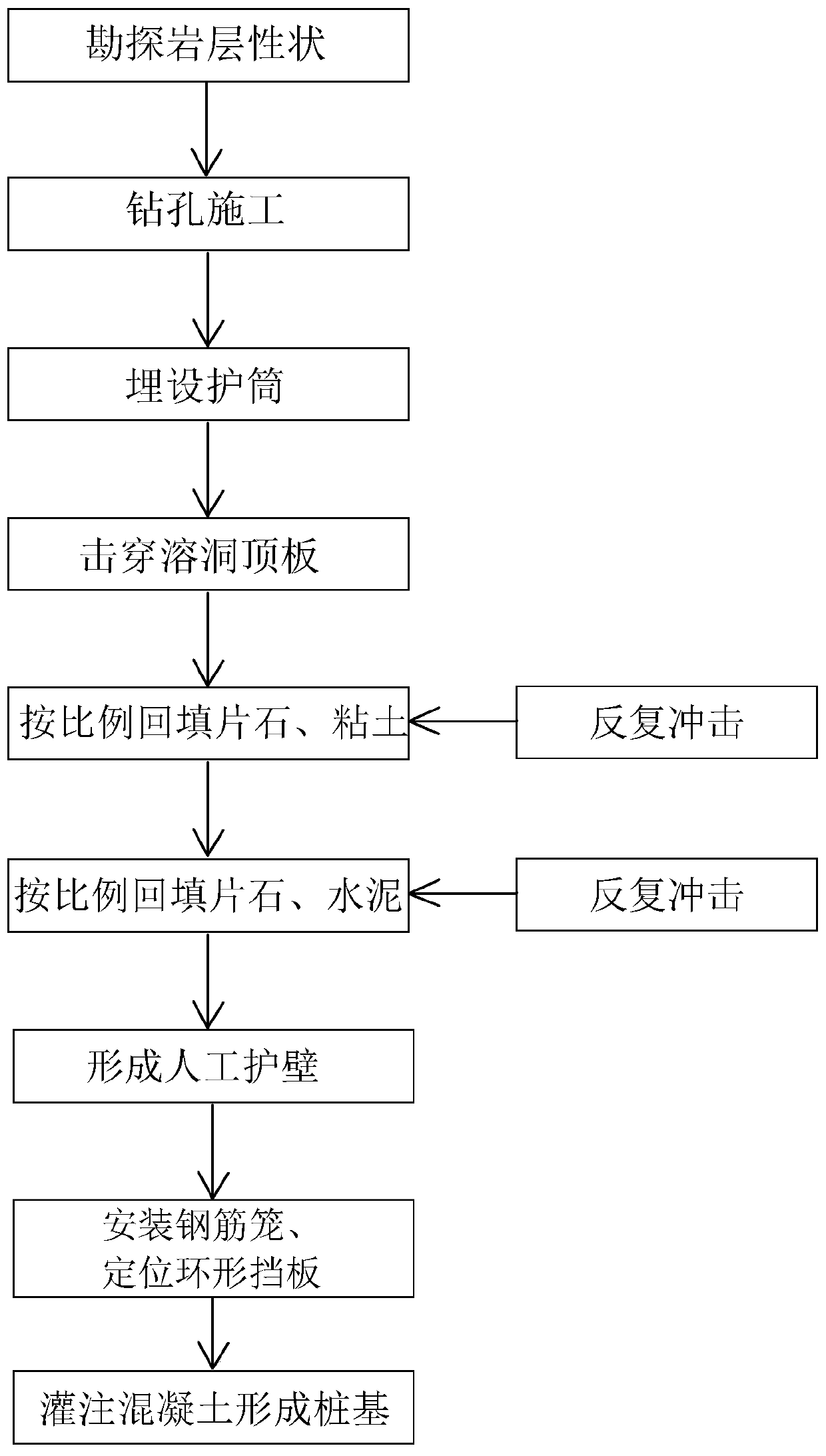
[0027] Reference figure 1 Taking the construction project of one stadium, one center and one stadium in Jiaoling County as an example, the embodiment provides a method for constructing karst cave pile foundations, including the following steps:
[0028] Step 1: Exploring the properties of the rock formations. Specifically, before the construction of each pile, advance drilling and combined with physical exploration methods are used to find out the properties of the foundation rock at the end of the pile, including the strength of the rock sample, whether there is a cave 6, the scale of the cave 6, and the location of the cave 6. The degree of breakage of the roof 5, the thickness of the roof 5, etc., among which the geophysical methods used include sound wave detection and geological radar detection.
[0029] According to the geological conditions explored in step 1, draw the distribution map of karst cave 6 and the distribution map of pile positions, so as to determine the depth and pile diameter of the construction pile position, arrange the drilling rig in place, and make full preparations for the construction.
[0030] Step 2: Construction of piles into holes to penetrate the roof 5 of the cavern 6. Use a drilling rig to open the hole. The position of the hole should correspond to the position of the advance drilling hole. During the drilling process, appropriate construction methods should be adopted according to the location of the cave 6, such as: The hole wall is squeezed more densely; when the distance of 2m from the top plate of the cave 6 is approaching, the impact should be low and light impact, slow impact to reduce the phenomenon of large area collapse of the cave 6.
[0031] According to the location and size of cave 6 by advance drilling exploration, when the thickness of the carbonaceous limestone on the roof 5 of cave 6 is less than 4D+0.5m (D is the pile diameter) and not more than 6m, the pile shall be constructed by punching through or underwater The blasting operation method penetrates the roof 5 of the cave 6 with high construction efficiency, can effectively penetrate the roof 5 and avoid the large area collapse of the cave 6.
[0032] In addition, during the pile hole construction, bury protective tubes in the soft soil layer 4, and bury each protective tube on the corresponding pile position. The center of the protective tube coincides with the center of the pile position, and the surrounding protective tube is backfilled with clay and compacted. . The protective tube is made of 5-8mm steel plate, its inner diameter is 1.2-2.0 meters, and the height is 2 meters. Its bottom is buried 1.5-2 meters below the ground, and the top of the protective tube is 0.2-0.5 meters above the ground. Open 1-2 overflow holes.
[0033] In the embodiment, in step 2 above, when the cave 6 is inclined or the probe stone appears to cause the drill bit to slide down the soft part to create an oblique hole, pour underwater concrete into the pile hole, and repeatedly impact with a small stroke hammer after the strength is formed. Until the pile hole is aligned. It is understandable that an excessively large stroke will result in out-of-round holes, resulting in oblique holes, so a stroke of 2-4m is generally appropriate.
[0034] In the embodiment, when the drill bit is stuck by the top plate 5 of the cave 6, a funnel-shaped steel casing can be used to run down the top of the drill bit along the rope to lead out the drill bit. After the drill bit is raised, use a small stroke to slowly repair the hole, and if necessary, backfill the rubble and clay to re-drill. After a stuck drill accident occurs, it is not advisable to force the drill bit to avoid breaking the machine, breaking the wire rope and dropping the drill bit. When the drill bit can move up and down, use the drill rig to lift the drill bit up and down, and use a crowbar to pull the big rope to make the drill bit rotate. Repeat for many times to lift the drill bit.
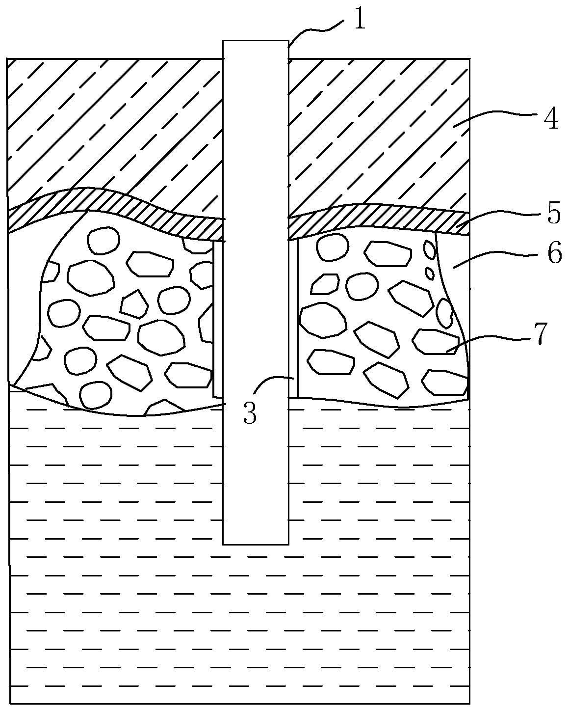
[0035] Step 3: After the karst cave 6 breaks through the slurry leakage, the filler 7 is backfilled. The filler 7 used includes flake stone and clay or a mixture of flake stone and cement. The material and proportion of the filler 7 are selected according to the actual situation. Generally, the leakage of grout can be solved by filling the flake stone and clay. In the impact hole formation, because some karst caves 6 are connected with underground rivers or other karst caves 6, the mud flows away quickly and the water head drops sharply, causing slurry leakage. Once there is slurry leakage, backfill the rubble and clay to make the wall in time, and immediately replenish water when necessary to prevent the water head from dropping.
[0036] Step 4: Continue drilling after the slurry leakage is blocked. Repeatedly impacting and backfilling the filler 7 until a protective wall is formed to block the cave 6 to prevent the cave 6 from leaking, so that the drill bit can smoothly pass through the cave 6 and then transfer to normal drilling. Since the filling amount of caves 6 of different properties is different, the number of constructions of backfilling and impact is selected according to the actual situation, until the artificial wall is formed in the pile hole so that the cave 6 no longer leaks.
[0037] In this embodiment, the specific method of building the wall of the pile hole is to fill the pile hole with a mixture of rubble and clay (ratio 1:2), the filling height is more than 2m above the top plate of the cave 6, and the cave is backfilled with low hammer and slow driving. 6 Around the inner pile wall, repeat the process until the bottom plate of the cave 6 is drilled with the normal stable footage; then backfilled with rubble and bagged cement (ratio 3:1), the filling height is 2m higher than the top plate of the cave 6, and the height The hammer hammer method squeezes the mixture of rubble and cement into the cave 6 and continues to combine the high hammer hammer method to impact the filler 7 when filling the filler 7 continuously, and repeat until it reaches the normal stable footage. The bottom plate of the cave 6 is dense and firm to avoid the leakage of the cave 6 and the drill bit enters the normal drilling after the construction of the cave is completed.
[0038] In another embodiment, flakes, clay and a whole package of cement (ratio 3:2:1) can be used for backfilling impact, with a small stroke of 0.5-0.8m, without circulating mud for a few minutes to make the backfill fully compact. Add grout to raise the water head to a normal height. After the initial cement has a certain strength, plug the leaking place and then use a small stroke to continue drilling to form an artificial mud-rock wall. Such repeated backfilling of flakes, clay and the whole package of cement, repeated impacts until the formation of mud stone wall and no more leakage. The wall construction method is suitable for large-area karst caves 6, to ensure that the mud does not run off, so that the borehole can pass through the karst area smoothly.
[0039] If cave 6 is found to be larger (cavity height> 3m), consider adopting the scheme of lowering the steel protective tube. This method is to punch the hole on one side and connect the high protective tube on the other side, and press or vibrate to sink into the drilled hole. When the pile hole passes through multiple caves 6 and the walls have been successfully built, and when the hole is punched below, the mud-rock protection wall formed above collapses and leaks and cannot be solved, the steel protective cylinder can follow up to this cave 6 to stop the leakage . The steel casing should have a certain rigidity, and the thickness of the steel plate should be 9mm. A single large karst cave 6 uses a single-layer casing, two large karst caves 6 use a double-layer casing, and so on. During construction, the reaming performance of the impact drill should be fully utilized to make the steel casing sink smoothly. The diameter of the drill bit is 3~125px larger than the outer diameter of the steel protective tube. After the protective tube is in place, the drill bit is changed to a drill bit diameter that meets the requirements for hole formation. If the percussion drill in the hard rock has a small expansion coefficient and cannot meet the sinking requirements of the protective tube, backfill and increase the diameter of the drill bit for secondary punching to ensure the smooth sinking of the steel protective tube. Sliding down requires that the pile hole be vertical without skew or necking.
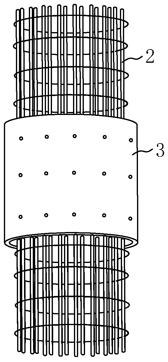
[0040] Step 5: Install the steel cage 2 and pour concrete to form the pile foundation 1. The steel cage 2 is equipped with a baffle 3 corresponding to the cave 6. When pouring concrete, the slump of the concrete should be 18~500px; the pouring pipe must be well-sealed, and the waterproof plug must be placed before pouring. The pouring of the concrete must be continuous and fast. The pile end is supported on the charcoal limestone layer that meets the requirements of the design code.
[0041] See figure 2 with 3 In the embodiment, the depth position of the cave 6 is measured, and a ring-shaped baffle 3 corresponding to the position of the cave 6 is set on the steel cage 2. The ring-shaped baffle 3 is welded to the steel cage 2, and the ring-shaped baffle 3 used is Steel plate, the thickness of the steel plate is 8mm-10mm. When installing the steel cage 2, use a two-point hoist to lift the steel cage 2, align the aperture, keep it vertical and put it into the pile hole slowly to avoid rotating the steel cage 2 or causing it to swing against the side wall. Position the steel cage 2 so that the ring The shaped baffle 3 is aligned with and covers the opening of the cave 6 and the concrete pouring is completed within 6 hours to prevent the collapse of the hole. In this way, the artificial wall protection and the annular baffle 3 make the structure of the clogged cave 6 more compact and firm, and prevent concrete from entering the cave 6 when the pile foundation 1 is poured, so that the pile foundation 1 is formed with higher quality.
[0042] The embodiments of the present invention are described in detail above with reference to the accompanying drawings. However, the present invention is not limited to the above-mentioned embodiments. Within the scope of knowledge possessed by those of ordinary skill in the technical field, various modifications can be made without departing from the purpose of the present invention. Kind of change.