Eureka AIR delivers breakthrough ideas for toughest innovation challenges, trusted by R&D personnel around the world.

Claw type hydrogen circulating pump

A circulation pump, hydrogen technology, applied in the direction of rotary piston pumps, pumps, pump components, etc., can solve the problems of reducing maintenance costs, reducing processing and assembly error rates, leakage, etc., to reduce maintenance costs, reduce error rates, structure well-designed effects

Pending Publication Date: 2019-10-11
烟台东德氢能技术有限公司
View PDF0 Cites 9 Cited by
  • Summary
  • Abstract
  • Description
  • Claims
  • Application Information

AI Technical Summary

Problems solved by technology

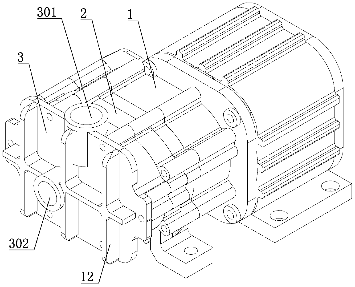
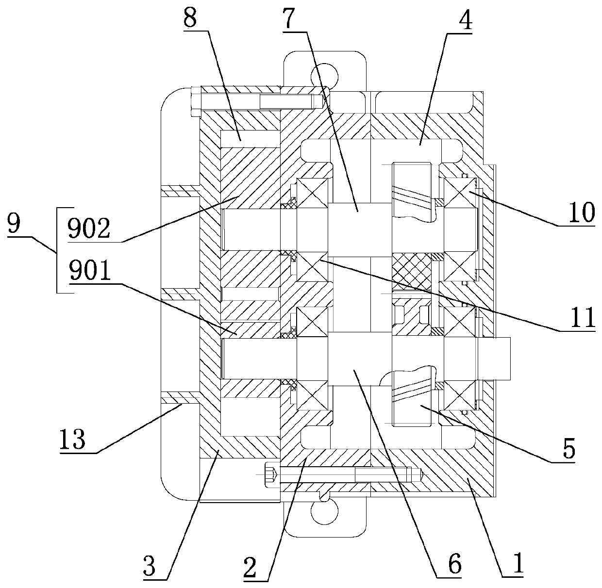
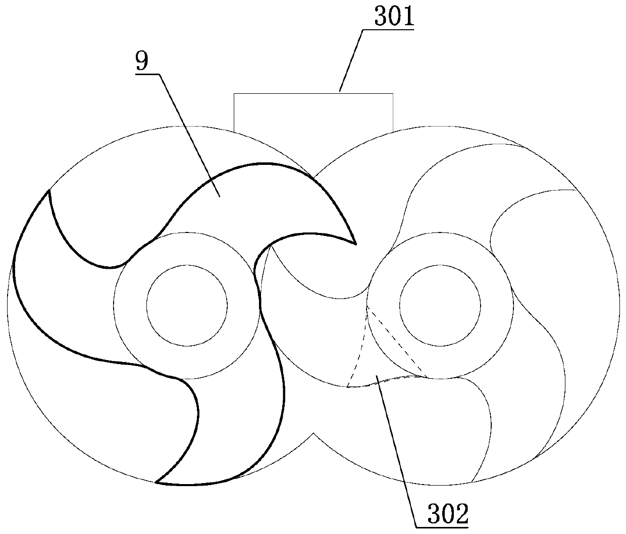
[0003] The invention provides a claw-type hydrogen circulation pump, which has a reasonable structural design, and the synchronous gear of the rotor adopts a new technology of non-metallic self-lubrication, which has the characteristics of high temperature resistance and no lubrication, so there is no need to add lubricating oil to the gear chamber , which realizes the oil-free operation of the hydrogen circulation pump, and solves the problem of lubricating oil leakage from the root; moreover, the self-lubricating gears made of non-metallic materials also have the advantages of wear resistance and low noise, and do not require the replacement of lubricating oil Maintenance is equivalent to achieving maintenance-free gears and reducing the corresponding maintenance costs; in addition, by optimizing the profile of the three-jaw rotor, the profile of the two three-jaw rotors is exactly the same, and complete interchangeable matching can be realized. The error rate of processing and assembling of the two claw rotors is greatly reduced, and the problems existing in the prior art are solved

Method used


Image

  • Claw type hydrogen circulating pump
  • Claw type hydrogen circulating pump
  • Claw type hydrogen circulating pump

Examples


Embodiment Construction

[0022] In order to clearly illustrate the technical features of this solution, the present invention will be described in detail below through specific implementation modes and in conjunction with the accompanying drawings.

[0023] In the following description, many specific details are set forth in order to fully understand the application, but the application can also be implemented in other ways different from those described here, therefore, the protection scope of the application is not limited by the specific details disclosed below. EXAMPLE LIMITATIONS.

[0024] In addition, in the description of the present application, it should be understood that the terms "center", "upper", "lower", "front", "rear", "left", "right", "vertical", "horizontal" ", "Top", "Bottom", "Inner", "Outer", "Axial", "Radial", "Circumferential" and other indicated orientations or positional relationships are based on the orientations or positional relationships shown in the drawings , is only f...


PUM


Abstract

The invention relates to a claw type hydrogen circulating pump. The claw type hydrogen circulating pump comprises a first shell body, a bearing end cover connected with the first shell body, and a second shell body connected with the bearing end cover, wherein a gear chamber is formed between the first shell body and the bearing end cover, two self-lubricating gears which are meshed with each other are arranged in the gear chamber, and no lubricating oil exists in the gear chamber; the two self-lubricating gears are correspondingly connected with a driving shaft and the driven shaft; a rotor chamber is formed between the bearing end cover and the second shell body, and two mutually matched three-jaw rotors are arranged in the rotor chamber. According to the claw type hydrogen circulating pump, the synchronous gears of the rotors adopt a novel technology of non-metal self-lubricating, and has the characteristics of high temperature resistance and no need of lubrication, therefore, lubricating oil does not need to be added in the gear chamber, the oil-free operation of the hydrogen circulating pump is realized, and the problem of the lubricating oil leakage is fundamentally solved; and moreover, the self-lubricating gears of non-metal material further has the advantages of wear resistance and low noise, the replacement maintenance of the lubricating oil is not needed, and equivalently, the maintenance-free of the gears is realized.

Description

technical field [0001] The invention relates to a claw type hydrogen circulation pump. Background technique [0002] Hydrogen circulation pumps in the prior art are mainly used in the field of fuel cells, in which two-claw and two-lobe Roots-type hydrogen circulation pumps are mainly used, but the rotors of the existing hydrogen circulation pumps are all driven by synchronous gears, and synchronous gears Lubricating oil is needed for lubrication, so it is necessary to design the gear chamber, add lubricating oil to the gear chamber, the synchronous gear in the gear chamber is connected to the rotor shaft through the connecting shaft, and an oil seal device needs to be designed between the gear chamber and the rotor chamber, but the hydrogen circulation pump is in In the actual use process, there are still situations and hidden dangers that lubricating oil seeps or leaks from the gear chamber to the rotor chamber. After the lubricating oil enters the rotor chamber, it will co...

Claims


Application Information

Patent Timeline
Patent Type & Authority Applications(China)
IPC IPC(8): F04C18/12F04C29/02F04C29/00
CPCF04C18/126F04C29/02F04C29/00
Inventor 邢子义马学龙王升科谢元豪王明田帅张勤宇
Owner 烟台东德氢能技术有限公司
Why Eureka
Eureka Blog
Learn More