A double-bolt locking mechanism

A locking mechanism and pin technology, applied in the direction of fixing devices, mechanical equipment, bolts, etc., can solve the problems of inconvenient insertion and extraction of pins, and achieve the effects of ensuring positioning accuracy, prolonging service life, and enhancing the ability to resist lateral forces

Active Publication Date: 2020-11-06
CHINA ELECTRONIC TECH GRP CORP NO 38 RES INST
View PDF6 Cites 0 Cited by
  • Summary
  • Abstract
  • Description
  • Claims
  • Application Information

AI Technical Summary

Problems solved by technology

[0004] The technical problem to be solved by the present invention is: the problem of inconvenient plug insertion and extraction in the prior art

Method used


Image

  • A double-bolt locking mechanism
  • A double-bolt locking mechanism
  • A double-bolt locking mechanism

Examples


Embodiment 1

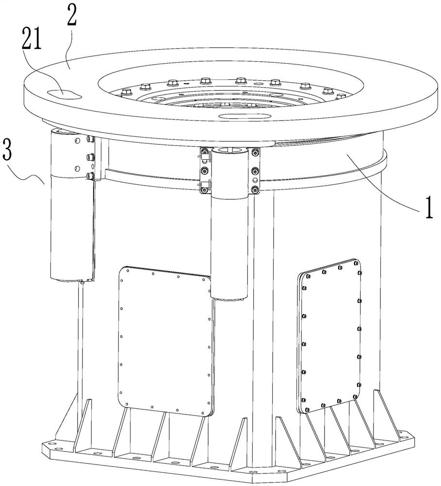
[0051] Such as figure 1 As shown, a double bolt locking mechanism includes a first component 1 capable of sliding relative to each other, a second component 2 , and two latch assemblies 3 installed on the first component 1 .

[0052] The first part 1 is fixed, the first part 1 is a rectangular parallelepiped base, the second part 2 is a rotatable disc, and the second part 2 rotates relative to the first part 1 .

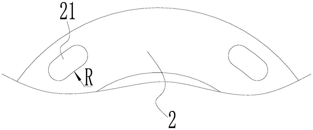
[0053] Such as figure 2 As shown, the second part 2 is provided with two positioning holes 21, and the positioning holes 21 are waist-shaped holes along the direction of the arc of rotation of the second part 2 in the length direction. figure 2 The middle symbol R indicates that the side of the positioning hole 21 is arc-shaped.

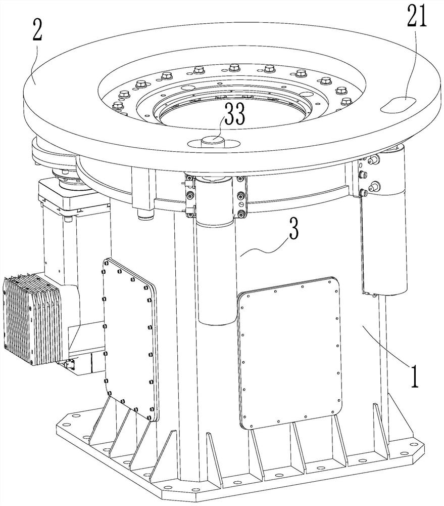
[0054] combine figure 1 , 8 -10, the bolt assembly 3 includes a bolt assembly body 31 installed on the first part 1, a bolt driving device 32 arranged on the bolt assembly body 31, and a bolt 33 hingedly arranged at the movable end of...

Embodiment 2

[0059] The difference between this embodiment and Embodiment 1 is:

[0060] Such as Figure 6 , 7 As shown, the first component 1 is fixed, the second component 2 slides linearly relative to the first component 1 , and the positioning hole 21 is a waist-shaped hole whose length direction is along the sliding direction of the second component 2 .

Embodiment 3

[0062] The difference between this embodiment and Embodiment 1 is:

[0063] It also includes a control unit (not shown in the figure), and the plug driving device 32 is connected to the control unit and controlled by the control unit. In this embodiment, the control unit adopts PLC, which can be purchased from the market, and the corresponding control can be realized by programming the PLC.

[0064] Such as Figure 8-10 As shown, the bolt assembly body 31 is provided with a limit switch 312 capable of limiting the stroke of the bolt 33, and the limit switch 312 is connected to the control unit. In this embodiment, the limit switch 312 is a proximity switch.

[0065] Specifically, such as Figure 9 As shown, there are two limit switches 312, which are distributed up and down, and avoidance holes are provided at the corresponding positions of the two limit switches 312. The upper limit switch 312 is located at the top when the latch 33 is retracted, and the latch 33 A through ...


PUM


Abstract

The invention discloses a double-bolt locking mechanism which comprises a first part and a second part capable of sliding opposite to each other, and two bolt assemblies mounted on the first part. Each bolt assembly comprises a bolt assembly body mounted on the first part, a bolt driving device arranged on the bolt assembly body and a bolt arranged at the moving end of the bolt driving device; twopositioning holes corresponding to the bolt are formed in the second part, the dimensions of the positioning holes in relative sliding directions of the first and second parts are greater than thoseof the bolts in corresponding directions, the two bolts can be separately inserted into the corresponding positioning holes, and the side walls of the two bolts can be separately attached to side wallof the sides, close to each other, of the two positioning holes simultaneously in the relative sliding directions of the first and second parts, or the side walls of the two bolts can be separately attached to the side walls of the sides, far away from each other, of the two positioning holes, simultaneously. The double-bolt locking mechanism disclosed by the invention has the advantage that thebolts are convenient to plug and high in locking efficiency.

Description

technical field [0001] The invention relates to the field of bolt locking, in particular to a double bolt locking mechanism. Background technique [0002] The bolt locking mechanism is used in structural equipment with relative movement, and uses the bolt inserted into the bolt hole to limit the relative movement, thereby limiting the undesired movement of the relatively moving equipment and protecting the safety of mechanical equipment and personnel. [0003] The commonly used latch structure is relatively simple, that is, a single latch is inserted into the latch hole. This latch structure requires the latch hole to run to the front of the latch. In order for the latch to be inserted smoothly into the latch hole, the relative position of the latch hole and the latch head must be very accurate. Although Now some pin heads are chamfered to facilitate the insertion of the angle deviation between the pin hole and the pin head within a certain range, but the range is limited, g...

Claims


Application Information

Patent Timeline
Patent Type & Authority Patents(China)
IPC IPC(8): F16B1/04F16B19/02
CPCF16B1/04F16B19/02
Inventor 郑传荣徐非骏张腊梅王贺何张强倪田荣李旺李红李付军桑青华张瑞珏杨帆吴后平周杨程翔宇
Owner CHINA ELECTRONIC TECH GRP CORP NO 38 RES INST
Why Eureka
Try Eureka