Fabrication and use of fiber grating sensing device and pressure ring using same
A fiber grating and sensing device technology, which is applied in the direction of force measurement, measurement device, measurement force, etc. by measuring the change of optical properties of materials when they are stressed, which can solve the problem of large temperature influence, data drift with time, and short service life. and other problems, to achieve the effect of reducing the influence of bending stress, reducing production costs and long service life
- Summary
- Abstract
- Description
- Claims
- Application Information
AI Technical Summary
Problems solved by technology
Method used
Image
Examples
Embodiment 1
[0059] refer to Figure 7-10 , a fiber grating sensing device, comprising a fiber grating sensor 41, a package rod 42 and a connecting nut 43, the middle section of the package rod 42 is provided with a longitudinal groove 44, and the fiber grating sensor 41 is placed in the longitudinal groove 44 Inside, the two ends of the package rod 42 are provided with threads 45, and the package rod 42 is connected to the connecting nut 43 through the threads 45 at both ends;
[0060] Described fiber grating sensor 41 comprises bare optical fiber one 46, bare optical fiber two 49, bare grating 48, capillary 47, and one end of described fiber grating sensor 41 is bare optical fiber one 46, and the length of described bare optical fiber one 46 is greater than 300mm, Described bare optical fiber one 46 passes through capillary tube 47 and exposes, and the other end of described fiber grating sensor 41 is bare optical fiber two 49, and described bare optical fiber two 49 passes through capil...
Embodiment 2
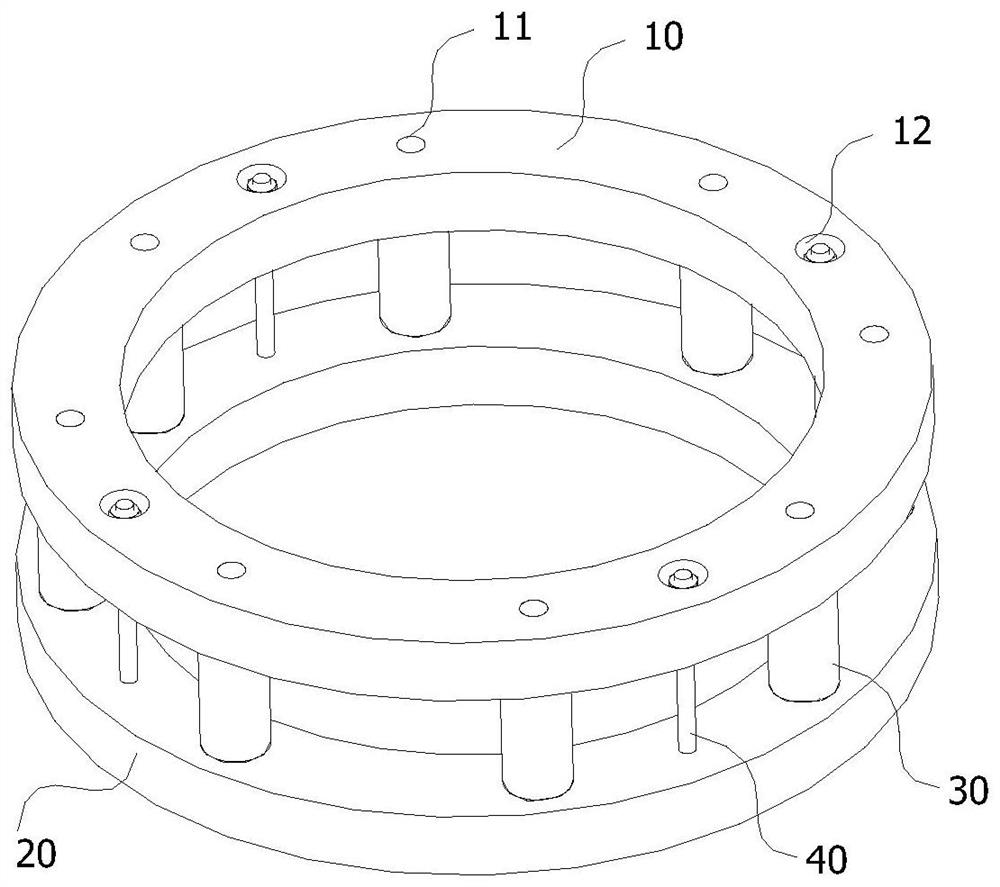
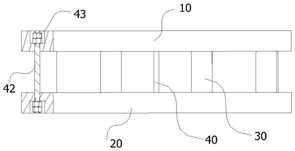
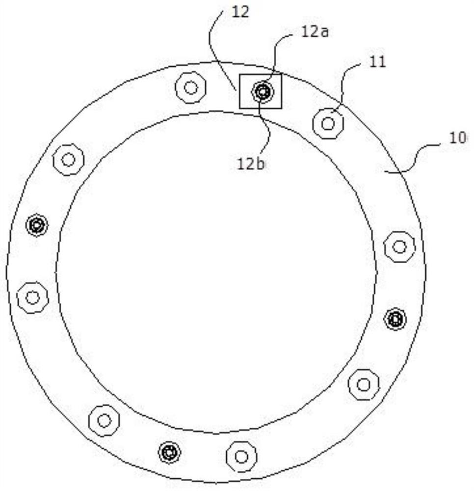
[0064] refer to Figure 1-6 , comprising the pressure ring of a fiber grating sensing device described in embodiment 1, the pressure ring also includes an upper support plate 10, a lower support plate 20, a load-bearing pillar 30, and the upper support plate 10 The lower support plate 20 is a center perforated annular plate with the same structure. The thickness of the upper support plate 10 and the lower support plate 20 is 20 mm to 30 mm, the circumferential width is 30 mm, and the material is stainless steel or 40 chromium. The hole diameters of the central perforations of the seat plate 10 and the lower support plate 20 are equal, and the hole diameters of the central perforations of the upper support plate 10 and the lower support plate 20 are larger than the diameter of the measured component, which is convenient for the measured component to pass through. In this embodiment, use When the cables of the cable-stayed bridge are stressed, the outer diameter of the anchor cu...
Embodiment 3
[0071] refer to Figure 1-10 , the manufacture method of pressure ring described in embodiment 2, concrete steps comprise:
[0072]Step 1. Select the range of the pressure ring according to the stress of the actual project, and determine the diameter of the load-bearing pillar 30. According to the formula (1) the number n of the load-bearing pillars (30), taking into account the symmetry, can be divisible by 4 An integer of , select the corresponding upper support plate 10 and lower support plate 20;
[0073]
[0074] In the formula, N represents the pressure that needs to be monitored in the full range of the pressure ring, r 1 Represents the radius of the load-bearing pillar (30), σ 1 Represents the material fatigue strength of the load-bearing pillar 30 during long-term service; select the corresponding upper support plate (10) and lower support plate (20);
[0075] In the present embodiment, when it is used for the stress of the cable-stayed bridge, it is assumed tha...
PUM
| Property | Measurement | Unit |
|---|---|---|
| diameter | aaaaa | aaaaa |
| depth | aaaaa | aaaaa |
| length | aaaaa | aaaaa |
Abstract
Description
Claims
Application Information
 - R&D
- Intellectual Property
- Life Sciences
- Materials
- Tech Scout
- Unparalleled Data Quality
- Higher Quality Content
- 60% Fewer Hallucinations
Browse by: Latest US Patents, China's latest patents, Technical Efficacy Thesaurus, Application Domain, Technology Topic, Popular Technical Reports.
© 2025 PatSnap. All rights reserved.Legal|Privacy policy|Modern Slavery Act Transparency Statement|Sitemap|About US| Contact US: help@patsnap.com


