Prime lens and imaging system thereof

A fixed-focus lens and lens technology, applied in the field of fixed-focus lenses and their imaging systems, can solve the problems of poor imaging effect of infrared and visible light confocal lenses, and achieve the effects of reduced tolerance sensitivity, excellent temperature performance, and reduced processing and assembly.

Pending Publication Date: 2019-10-11
舜宇光学(中山)有限公司
View PDF0 Cites 5 Cited by
  • Summary
  • Abstract
  • Description
  • Claims
  • Application Information

AI Technical Summary

Problems solved by technology

[0003] The purpose of the present invention is to provide a fixed focus lens to solve the problem of poor imaging effect of infrared visible light confocal lens

Method used


Image

  • Prime lens and imaging system thereof
  • Prime lens and imaging system thereof
  • Prime lens and imaging system thereof

Examples


Embodiment 1

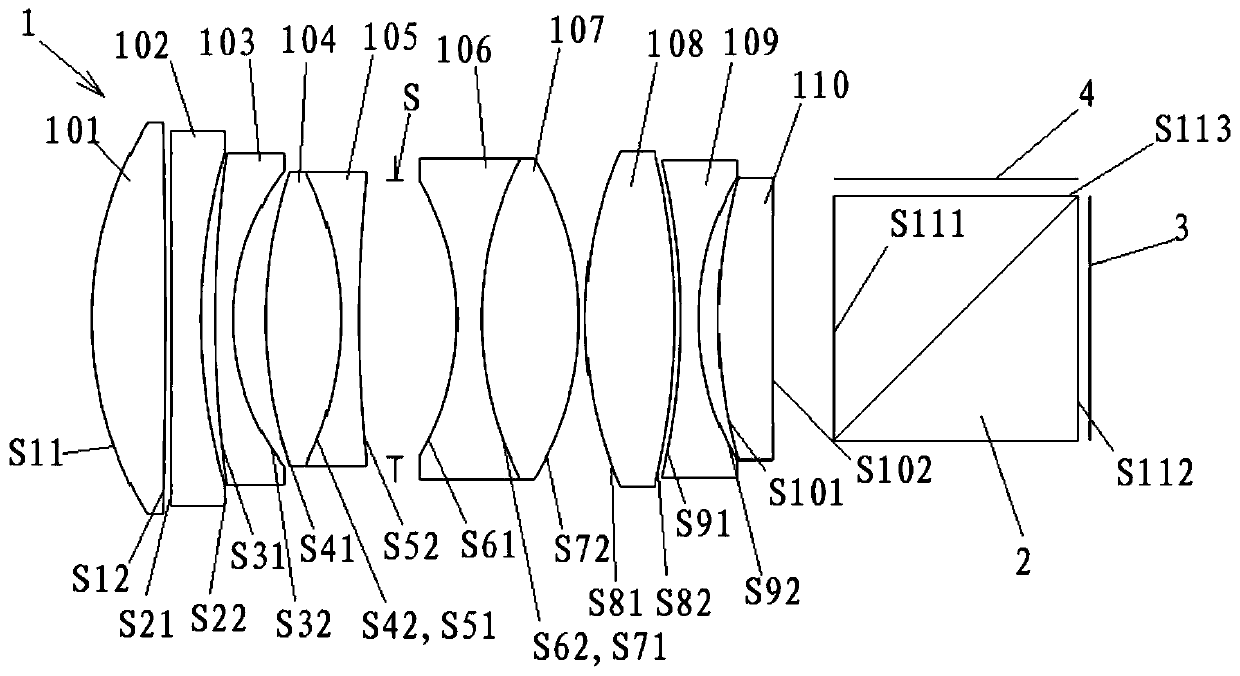
[0083] based on figure 1 The structure of the fixed-focus lens shown is illustrative of this embodiment. see figure 1 As shown, for the convenience of describing the embodiments of the present invention, the mirror surfaces of the lenses of the fixed-focus lens of the present invention are numbered from the object side to the image side. therefore. S11 is the object side of the first lens 101 near the object side, S12 is the image side of the first lens 101 near the image side; S21 is the object side of the second lens 102 near the object side, and S22 is the image of the second lens 102 near the image side Side; S31 is the object side of the third lens 103 close to the object side, S32 is the image side of the third lens 103 close to the image side; S41 is the object side of the fourth lens 104 close to the object side, and S42 is the fourth lens 104 close to the image side S51 is the object side of the fifth lens 105 near the object side, S52 is the image side of the fift...

Embodiment 2

[0097] based on Figure 4 The structure of the fixed-focus lens shown is illustrative of this embodiment. Such as Figure 4 As shown, for the convenience of describing the embodiment of the present invention, the mirror surface of the lens of the fixed-focus lens of the present invention is numbered from the object side to the image side, and its numbering rule is the same as that of the foregoing embodiment 1, and will not be repeated here.

[0098] Each parameter of fixed-focus lens of the present invention is as follows:

[0099] f 1 =63.115;f 2 = -136.645; f 3 = -96.996; f 4 =67.171;f 5 =-63.386; f 6 = -65.799; f 7 =63.135; f 8 = 43.781; f 9 = -46.219; f 10 =81.994;

[0100] f 45 = 6325.748; f 12 = 102.538; f 67 = -209.072; f 89 = 238.940; f 123 = 606.002; f 8910 =68.732;

[0101] f3 / f 10 = -1.18; f 67 / f 12 = -2.04; f 89 / f 67 = -1.14; f 123 / f 8910 =8.82;

[0102] Nd1=1.91; Nd4=1.44; Nd7=1.44; Nd8=1.89;

[0103] (Nd1-1) / (Nd4-1)=2.08; (Nd1-1) / ...

Embodiment 3

[0111] based on Figure 7 The structure of the fixed-focus lens shown is illustrative of this embodiment. Such as Figure 7 As shown, for the convenience of describing the embodiment of the present invention, the mirror surface of the lens of the fixed-focus lens of the present invention is numbered from the object side to the image side.

[0112] Each parameter of fixed-focus lens of the present invention is as follows:

[0113] f 1 = 47.617; f 2 = -63.756; f 3 = -199.154; f 4 =52.515; f 5 = -41.626; f 6 = -32.940; f 7 = 45.922; f 8 = 45.728; f 9 = -49.106; f 10 =82.088;

[0114] f 45 = -317.774; f 12 = 134.951; f 67 = -248.883; f 89 = 232.767; f 123 =287.091; f 8910 =68.575;

[0115] f 3 / f 10 = -2.43; f 67 / f 12 = -1.84; f 89 / f 67 = -0.94; f 123 / f 8910 =4.19;

[0116] Nd1=1.86; Nd4=1.59; Nd7=1.59; Nd8=1.92;

[0117] (Nd1-1) / (Nd4-1)=1.45; (Nd1-1) / (Nd7-1)=1.45; (Nd8-1) / (Nd4-1)=1.55; (Nd8-1) / (Nd7 -1) = 1.55.

[0118] The system parameters are: ...


PUM


Abstract

The invention relates to a prime lens and an imaging system thereof, the prime lens comprises a first lens (101), a second lens (102), a third lens (103), a fourth lens (104) with positive focal power, a fifth lens (105) with negative focal power, a sixth lens (106) with negative focal power, a seventh lens (107) with positive focal power, an eighth lens (108), a ninth lens (109) and a tenth lens(110) with positive focal power, which are sequentially arranged from an object side to an image side; the fourth lens (104) and the fifth lens (105) are disposed in a mutually matching manner; and the sixth lens (106) and the seventh lens (107) are disposed in a mutually matching manner. The prime lens provided by the invention can effectively correct the chromatic aberration of a visible light path at a low cost via a simple structure and helps to reduce the spherical aberration of an infrared light path, and the performance of two paths is simultaneously improved by the simple structure.

Description

technical field [0001] The invention relates to the field of optical imaging, in particular to a fixed-focus lens and an imaging system thereof. Background technique [0002] At present, the infrared and visible light confocal lenses generally have such shortcomings: low lens pixels, high and low temperature virtual focus, and many noises in low-light environments. And existing infrared-visible light confocal lens mostly needs to adopt some higher price abnormal dispersion and high refractive index material lens to realize confocal plane clear imaging in order to overcome the shortcoming of above-mentioned existence. This kind of lens is not only difficult to design and high in development cost, but also difficult to image infrared and visible light with optimal resolution at the same time. . Contents of the invention [0003] The purpose of the present invention is to provide a fixed-focus lens to solve the problem of poor imaging effect of the infrared-visible light co...

Claims


Application Information

Patent Timeline
Patent Type & Authority Applications(China)
IPC IPC(8): G02B13/00G02B13/14
CPCG02B13/0015G02B13/008G02B13/14
Inventor 聂路鑫范家永翟林燕梁伟朝邹文镔
Owner 舜宇光学(中山)有限公司
Why Eureka
Try Eureka