
A flameless heater

A heater and flameless technology, applied in the direction of induction heating, ohmic resistance heating, induction heating devices, etc., can solve the problems of low heating efficiency of the heating gun head, high loss of magnetic force lines, and slow heating speed, so as to avoid the breakage of the condenser tube, High heating efficiency and fast heating effect

Active Publication Date: 2021-11-30
握友智能科技(深圳)有限公司
View PDF6 Cites 0 Cited by
  • Summary
  • Abstract
  • Description
  • Claims
  • Application Information

AI Technical Summary

Problems solved by technology

When the heat gun head arranged in this way is heated to the metal to be heated, the loss of the magnetic force line is more, thereby causing the heating efficiency of the heat gun head to be low, and the heating speed is slow, and the simple U-shaped tube is used to return the cooling liquid, and the volume it occupies is relatively small. Large, it is prone to breakage and damage when the extension distance is a little longer, so it needs to be improved

Method used


Image

  • A flameless heater
  • A flameless heater
  • A flameless heater

Examples


Embodiment 1

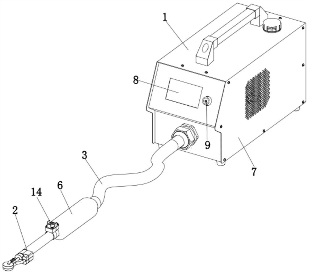
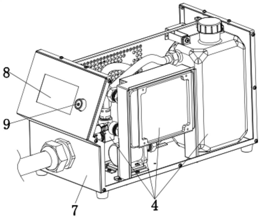
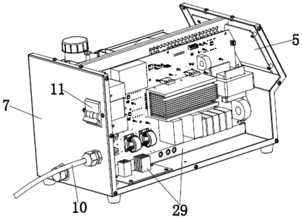
[0033] Embodiment 1: This embodiment relates to a flameless heater, such as Figure 1-3 As shown, it includes: a host 1 , a heating gun head 2 and a flexible pipe 3 .

[0034] Such as Figure 1-3 As shown, a cooling system 4 and a control system 5 are arranged in the main engine 1 . The cooling system 4 is used to realize the circulation of the coolant in the host 1 in the heating gun tip 2 , so as to cool down the heating gun tip 2 and prolong the service life of the heating gun tip 2 . The control system 5 is used to control the flameless heater, so as to ensure the safety of users and improve the use safety of the flameless heater. The heat gun head 2 is arranged on one side of the main machine 1, and the heat gun head 2 is used for heating the metal to be heated. One end of the flexible pipe 3 is sealed and assembled with the liquid outlet of the cooling system 4, and the other end is sealed and assembled with the heating gun head 2. The flexible pipe 3 is used to trans...

Embodiment 2

[0043] Embodiment 2: The difference between this embodiment and Embodiment 1 is that, as Figure 8-11 As shown, in this embodiment, the heating conductive member 20 is a heating conductive block 28 , one end of the heating conductive block 28 is assembled with the second mounting head 18 , and the other end is assembled with the third mounting head 19 . A guide groove is provided in the heating conductor 20 , and the guide groove is used to communicate with the through grooves of the third installation head 19 and the second installation head 18 , so as to realize the circulation and backflow of the cooling liquid. The heating conduction block 28 is arranged on the upper end of the first installation head 17 (referring to as Figure 8 , 9 ) or side-end (refer to eg Figure 10 , 11 ). When the heating conduction element 20 is a heating conduction block 28 , the magnetism collecting device 15 includes: a magnetic element 25 embedded on the heating conduction element 20 . Th...


PUM


Abstract

A flameless heater relates to the technical field of flameless heating. It includes: a host, a host, a heating gun head arranged on one side of the host, and a flexible pipe; the heating gun head includes: a condensation pipe, at least one sub-pipe is arranged in the condensation pipe, and there is an interval between the condensation pipe and the sub-pipe; On one side of the condensing tube, one end is assembled with the sub-pipe, and the other end is assembled with the condensing tube; the switch button is arranged on the other side of the condensing tube; and, it is arranged on the heating head and is located between the heating head and the Magnetic gathering device at the position of metal contact. Adopting the above-mentioned technical scheme can not only reduce the overall volume of the heating gun head, so that the heating gun head can be used in narrow slits, but also reduce the damage of the magnetic force line, and has a wide range of applications, a large operating space when used, and a long service life. The advantages of high heating efficiency and fast heating speed.

Description

technical field [0001] The invention relates to the technical field of flameless heating, in particular to a flameless heater. Background technique [0002] A flameless heater is a device that uses the principle of electromagnetic induction to convert electrical energy into heat energy. The electromagnetic controller rectifies the 220V, 50 / 60Hz alternating current into direct current, and then converts the direct current into high-frequency high-voltage electricity with a frequency of 40-80KHz. The high-speed high-frequency high-voltage current flowing through the coil will produce high-speed alternating current. Magnetic field, when the magnetic field lines in the magnetic field pass through the magnetic metal material, countless small eddy currents will be generated in the metal body, so that the metal material itself will heat itself at a high speed, thereby achieving the purpose of heating the metal material. [0003] The heating gun head is an important accessory of th...

Claims


Application Information

Patent Timeline
Patent Type & Authority Patents(China)
IPC IPC(8): H05B6/14
CPCH05B6/14H05B2206/02
Inventor 武宁
Owner 握友智能科技(深圳)有限公司
Learn More