Integrated flushing drainage tube special for sternal infection wound

An integrated, drainage tube technology, applied in the field of medical devices, can solve the problems of complex operation, poor effect, inconvenient tube care, easy infection, etc., to reduce the chance of installation steps and skin incision infection, mature industrial manufacturing technology, and avoid blockage Effect

Pending Publication Date: 2019-10-15
THE FIRST AFFILIATED HOSPITAL OF SUN YAT SEN UNIV
View PDF0 Cites 0 Cited by
  • Summary
  • Abstract
  • Description
  • Claims
  • Application Information

AI Technical Summary

Problems solved by technology

[0003] When the existing mechanical drainage tube is used, firstly, visceral and retrosternal operations are increasing day by day. It is more common for elderly, malnourished, diabetic, COPD, and bypass patients to have non-union of sternal incision after internal mammary artery extraction. The patient base is large, and sternal incision Poor healing affects postoperative recovery, increases hospitalization time and medical expenses, and patients are often in great pain due to long hospitalization time. Secondly, one irrigation tube and two drainage tubes need to be placed after sternal debridement. The ready-made commercial pipeline needs to be modified with other pipelines, the operation is complicated and the effect is poor, and the multiple pipelines increase the workload of doctors and nurses and the risk of infection. Finally, it takes a long time to flush and drain the incision after sternal debridement, and often requires 1-2 weeks, it is inconvenient to care for multiple pipes, and it is easy to be infected

Method used


Image

  • Integrated flushing drainage tube special for sternal infection wound
  • Integrated flushing drainage tube special for sternal infection wound

Examples


Embodiment Construction

[0017] The following will clearly and completely describe the technical solutions in the embodiments of the present invention with reference to the accompanying drawings in the embodiments of the present invention. Obviously, the described embodiments are only some, not all, embodiments of the present invention.

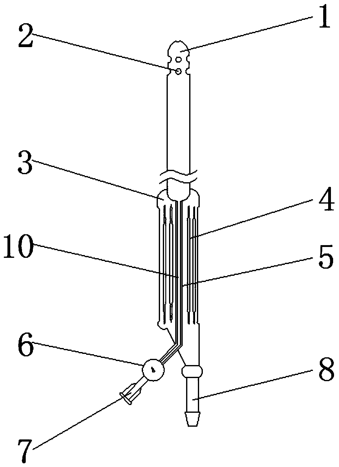
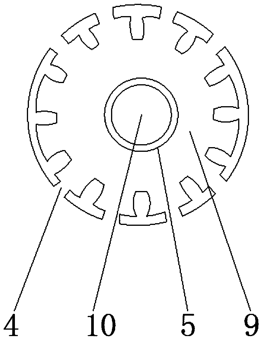
[0018] Such as Figure 1-2 As shown, an integrated flushing and drainage tube specially used for sternal infected wounds includes a flushing chamber 5, the outer surface of the flushing chamber 5 is provided with a drainage chamber body 3, and the outer surface of the drainage chamber body 3 is provided with a drainage chamber grille The inner wall of the flushing chamber 5 is provided with a flushing chamber inner tube 10, the inner wall of the drainage chamber body 3 is provided with a drainage chamber 9, and one end of the flushing chamber 5 is provided with a flushing chamber speed limiter 6 and a flushing liquid connector of the flushing chamber. 7, and the flus...


PUM


Abstract

The invention discloses an integrated flushing drainage tube special for a sternal infection wound, which comprises a flushingcavity.A drainage cavity part is arranged onthe outer surface of the flushingcavity, a drainage cavity grid-shaped opening is formed in the outer surface of the drainage cavity part,a flushing cavity inner tube is arranged onthe inner wall of the flushing cavity, a drainagecavity is arranged onthe inner wall of the draining cavitypart, one end of the flushing cavity is provided with a flushing cavity speed limiter and a flushing cavity flushing fluid joint,and the flushing cavity flushing fluid joint is located on one side of the flushing cavity speed limiter. According to the integrated flushing drainage tube special forthe sternal infection wound, the flushingtube and the drainage tubeare integrally designed, so that the mounting steps can be reduced, the probability of infection of a skin incision is decreased, the speed limiter is arranged to facilitate theadjustment offlushing speed according to illnessstates, 24-hour continuous flushing is available, the forming of the drainage cavity grid-shaped opening can effectively drain wound secretion and necrotic tissue to avoid clogging ,and the better use prospects are brought.

Description

technical field [0001] The invention relates to the field of medical devices, in particular to an integrated flushing and drainage tube specially used for sternal infected wounds. Background technique [0002] The drainage tube is used for clinical surgical drainage. It guides the pus, blood, and liquid accumulated between human tissues or body cavities to the outside of the body to prevent postoperative infection and promote wound healing. There are many types of surgical drainage tubes used in clinical practice. , some are used for catheterization, some are used for wounds, chest cavity, brain cavity, gastrointestinal tract, biliary tract and so on. In vitro, it prevents postoperative infection and affects wound healing, and is widely used in medical operations. [0003] When the existing mechanical drainage tube is used, firstly, visceral and retrosternal operations are increasing day by day. It is more common for elderly, malnourished, diabetic, COPD, and bypass patient...

Claims


Application Information

Patent Timeline
Patent Type & Authority Applications(China)
IPC IPC(8): A61M25/14A61M3/02
CPCA61M3/0283A61M25/0023A61M25/007
Inventor 梁孟亚
Owner THE FIRST AFFILIATED HOSPITAL OF SUN YAT SEN UNIV
Why Eureka
Try Eureka