
Multistage pyrite water-saving sawtooth wave jig gravity separator

A technology of pyrite and sawtooth wave, which is applied in the field of multi-stage pyrite water-saving sawtooth wave jigging gravity separator, can solve the problems of large and easily damaged diaphragm, waste of water resources, high energy consumption, etc., and achieve high beneficiation efficiency, The effect of low energy consumption and simple principle of mineral separation

Active Publication Date: 2020-06-09
安徽省红顺新材料科技有限责任公司
View PDF7 Cites 0 Cited by
  • Summary
  • Abstract
  • Description
  • Claims
  • Application Information

AI Technical Summary

Problems solved by technology

[0003] At present, the common sheet of the existing hydraulic jigging gravity separator makes the water medium vibrate in a sawtooth wave through the agitation of the diaphragm at the bottom of the jigging chamber. Since the diaphragm needs to overcome the pressure and gravity of the medium water, each diaphragm is driven by a separate motor Agitation has the disadvantages of high energy consumption, high pressure on the diaphragm and easy damage; and when separating the concentrate, it is necessary to discharge the medium water in the jigging chamber, which has the disadvantage of wasting water resources. In order to overcome the above-mentioned Deficiency, the inventor designed a super pyrite water-saving sawtooth wave jigging re-separator with ingenious structure, simple principle, single motor and double jigging chamber, capable of continuous pyrite ore separation, and high beneficiation efficiency

Method used


Image

  • Multistage pyrite water-saving sawtooth wave jig gravity separator
  • Multistage pyrite water-saving sawtooth wave jig gravity separator
  • Multistage pyrite water-saving sawtooth wave jig gravity separator

Examples


Embodiment Construction

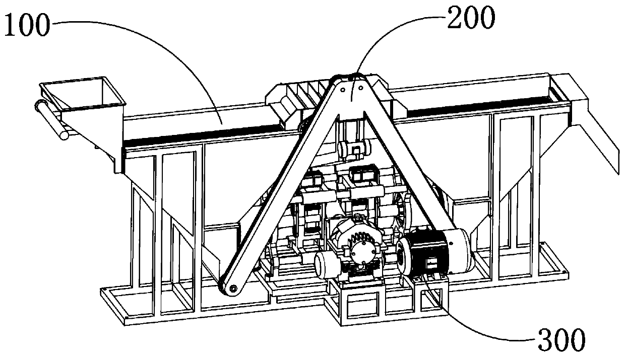
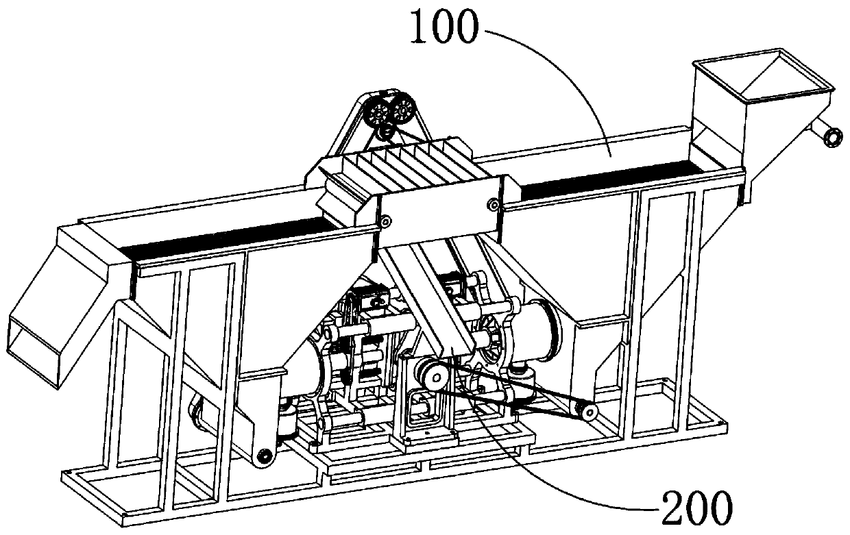
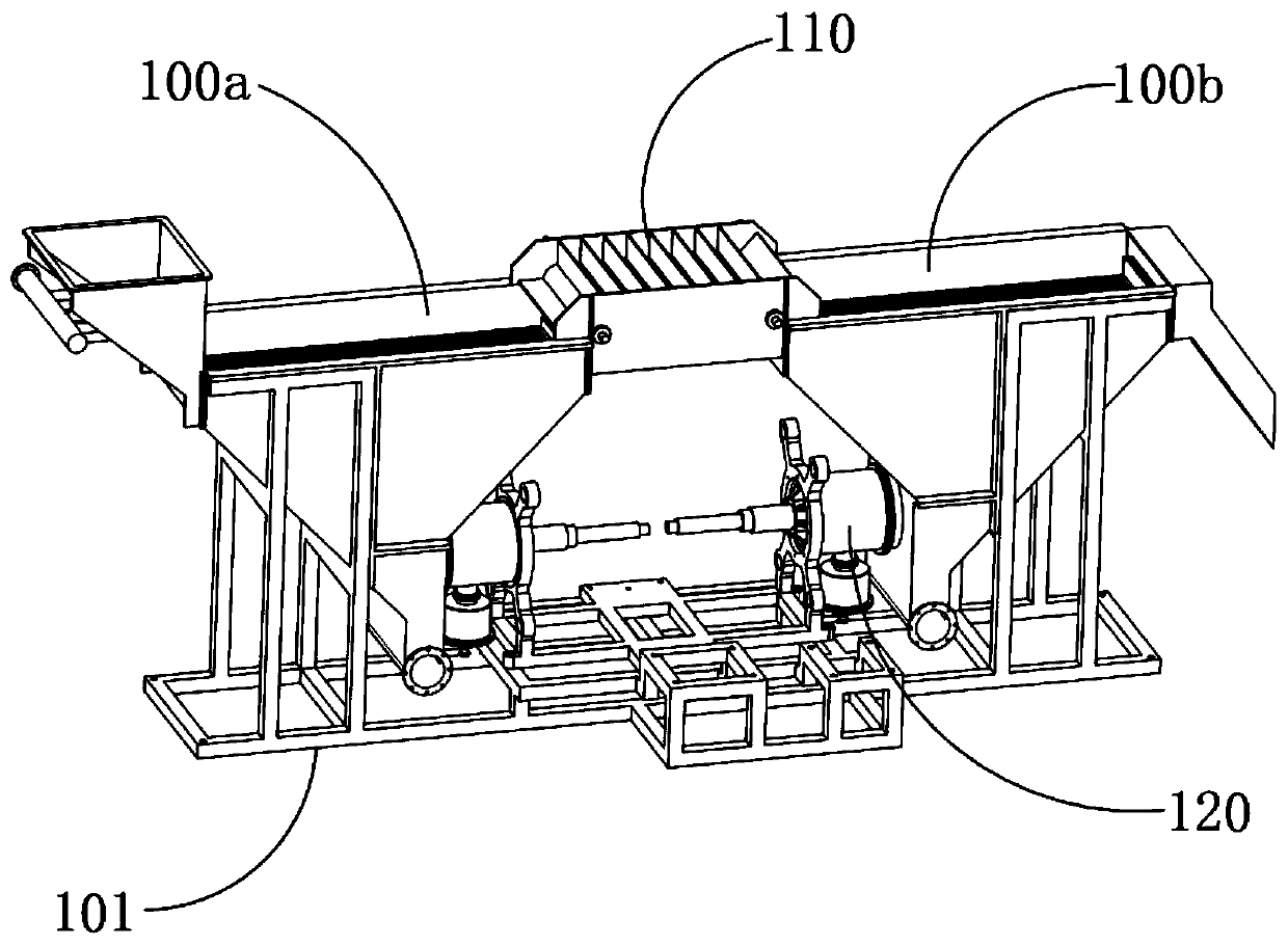
[0061] Multi-stage pyrite water-saving sawtooth wave jigging gravity separator, which includes a jigging box 100 with a V-shaped structure with an upward opening and filled with medium water inside, a discharge device 200, a power drive device 300, and a jigging box 100 It is composed of the first jigging box 100a and the second jigging box 100b arranged symmetrically. The first jigging box 100a is used to receive the mixture of pyrite and waste rock monomers and carry out concentrate gravity separation, and the second jigging box The box 100b is used to carry out secondary concentrate re-selection of the mixture of pyrite and waste rock monomers and to discharge the tailings. Between the openings of the first jigging box 100a and the second jigging box 100b, there is a The conveying mechanism 110, the side of the jigging box 100 near its bottom is provided with an agitating mechanism 120 for vibrating the internal medium water, and the discharge device 200 is used to dehydrate...


PUM


Abstract

The invention provides a multi-stage pyrite water-saving sawtooth wave jigging gravity selection machine. The multi-stage pyrite water-saving sawtooth wave jigging gravity selection machine comprisesjigging boxes which are each of a V-shaped structure with an upward opening and is internally filled with medium water, a discharging device and a power driving device, wherein the jigging box is composed of a first jigging box and a second jigging box which are symmetrically arranged left and right, the first jigging box is used for receiving a mixture of pyrite and waste rock monomer and carrying out concentrate reselection, the second jigging box is used for carrying out secondary concentrate reselection on the mixture of the pyrite and the waste rock monomer and discharging tailings, and aconveying mechanism for connecting the opening of the first jigging box and the opening of the second jigging box is arranged between the opening of the first jigging box and the opening of the second jigging box; and an agitation mechanism used for vibrating the inner medium water is arranged on the side face, close to the bottom, of the jigging box, the discharging device is used for dehydrating and discharging the concentrate deposited at the bottom of the jigging box, and the power driving device is used for providing driving power for the conveying mechanism, the agitation mechanism andthe discharging device.

Description

technical field [0001] The invention relates to a mineral dressing jigging machine, in particular to a multistage pyrite water-saving sawtooth wave jigging re-separator. Background technique [0002] The hydraulic jigging gravity separator is a gravity beneficiation process that uses the vertical alternating water flow caused by strong vibration to layer the ore particles according to the relative density and collect light and heavy minerals separately by appropriate methods to achieve the purpose of separation. During the process, the pyrite raw ore is crushed by the crusher to the optimum particle size for the rod mill, and then transported to the rod mill for grinding by the belt conveyor, so that the pyrite and waste rock are separated, and the pyrite and waste rock The single-head mixture is conveyed to the hydraulic jig by a belt conveyor for gravity separation, and the concentrate (pyrite) and tailings (waste rock monomer and a small amount of pyrite) are obtained fro...

Claims


Application Information

Patent Timeline
Patent Type & Authority Patents(China)
IPC IPC(8): B03B5/24B03B5/12
CPCB03B5/12B03B5/24
Inventor 王和能
Owner 安徽省红顺新材料科技有限责任公司
Learn More