
A cross-link lifting structure, bed frame and nursing bed

A lifting structure and cross-link technology, applied in the field of nursing beds, can solve problems such as overloading of telescopic elements

Active Publication Date: 2021-03-30
永康中科爱司米医疗科技有限公司
View PDF7 Cites 0 Cited by
  • Summary
  • Abstract
  • Description
  • Claims
  • Application Information

AI Technical Summary

Problems solved by technology

[0005] Therefore, the technical problem to be solved by the present invention is to overcome the defect that the cross-link lifting structure in the prior art tends to cause the telescopic element to be overloaded during use, and to provide a cross-link lifting structure that can better protect the telescopic element
[0006] The technical problem to be solved by the present invention is to overcome the defect that the bed frame in the prior art tends to cause the telescopic element to be overloaded during use, and then provide a bed frame that can better protect the telescopic element
[0007] The technical problem to be solved by the present invention is to overcome the defect that the nursing bed in the prior art tends to cause the telescopic element to be overloaded during use, and then provide a nursing bed that can better protect the telescopic element

Method used


Image

  • A cross-link lifting structure, bed frame and nursing bed
  • A cross-link lifting structure, bed frame and nursing bed
  • A cross-link lifting structure, bed frame and nursing bed

Examples


Embodiment 1

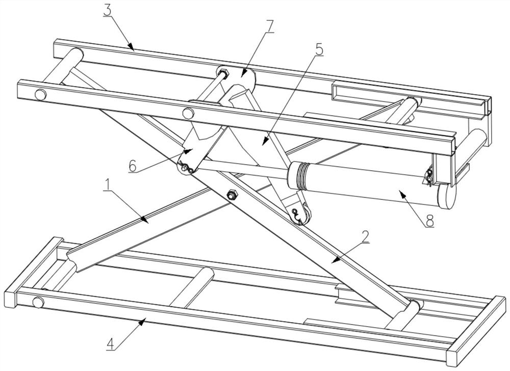
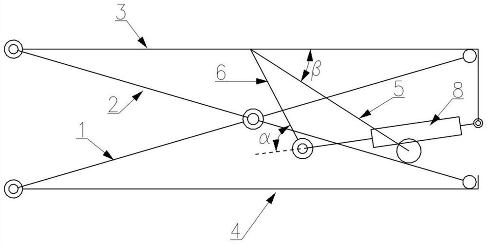
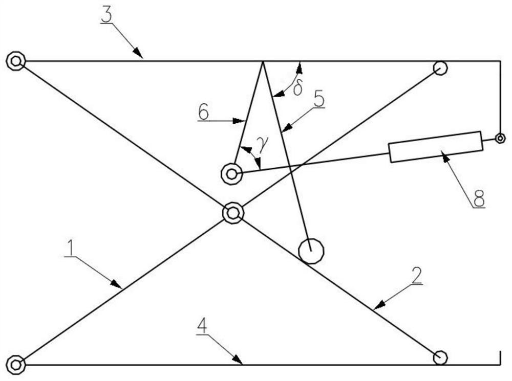
[0058] Such as Figure 1 to 3 As shown in the first embodiment provided by the present invention, the present embodiment provides a cross-link lifting structure. As described in the context, the cross-link lifting structure in the prior art is easy to cause damage to the telescopic element, and the technician usually selects a large thrust of the extensive thrust, but it also causes unnecessary waste of production resources. The crosslink lifting structure provided in this embodiment is well solved the above problems.

[0059] This embodiment includes the first link 1 and the second link 2, the first link 1 and the second link 2 intersect together in Type X; also includes a bracket 3 and a frame 4, a frame 4 On the ground, the bracket 3 is used to support the weight above. Both ends of the bracket 3 are mounted on the upper end of the first link 1 and the second link 2. The upper end of the first link 1 slides on one end of the bracket 3, and the upper end of the second link 2 is h...

Embodiment 2

[0073] Such as Figure 4 As shown, in Example 2, which is provided for the present invention, the present embodiment provides a bed frame. Including the upper frame 9, both ends of the upper frame 9 are respectively mounted, respectively, the cross-link lifting structure described in Embodiment 1, respectively. The bed frame can be rising, lowered, tilted, and other actions under the drive of the cross lifting structure.

[0074] In order to avoid the upper frame 9, he slipped from the bracket 3 during the inclination. In this embodiment, the inclined limit structure 10, such as Figure 5 As shown, the inclined limit structure 10 includes a curved guide rail 11, which is fixed to the upper frame 9, has a curved slide; the roller 12 is fixed to the bracket 3, during the upper frame 9 tilt, The rollers 12 are adapted to slide in the slot of the curved rail 11, and the upper frame 9 is positioned to avoid the sliding of the upper frame 9.

[0075] The present embodiment is due to the...

Embodiment 3

[0077] This embodiment provides a care bed, including a bed, and the bed plate is laid in the upper surface of the upper frame 9 in Example 2. The present embodiment is due to the installation of the crosslink lifting structure described in Embodiment 1, thereby also has all the advantages of the crosslink lifting structure in Example 1.


PUM


Abstract

The invention relates to the technical field of lifting devices, in particular to a cross connecting rod lifting structure, a bedstead and a nursing bed with the bedstead. The cross connecting rod lifting structure comprises a first connecting rod, a second connecting rod, a seat frame, a bracket, a telescopic element and a swinging piece. The length of a short arm and the length of a long arm jointly satisfy the following requirements: when the bracket is at the lowest point, the lift of the bracket resulting from the force exerted by the telescopic element on the short arm is greater than the load of the bracket. The cross connecting rod lifting structure provided by the invention can play a better protection effect on the telescopic element, has better fatigue resistance, is low in self-locking probability, and can descend to a lower height.

Description

Technical field [0001] The present invention relates to the technical field of lifting devices, and more particularly to a cross link lifting structure and a bed frame and a nursing bed having the bed. Background technique [0002] Cross link lifting structure is a common lifting structure, widely used in various areas of production, such as scaffolding, operating table, care bed, etc. There is a cross-link lifting structure that is driven by a swing arm structure and a telescopic element, including a first link and a second link attached together, and mounted on the first link and the second connection. The upper end of the upper end of the rod, the lower end of the first link and the second link is mounted on the frame. The upper end of the first link and the upper end of the second link are respectively hinged at one end of the frame and the bracket, and the upper end of the first link is slid to be mounted on the other end of the bracket, and the lower end of the second link ...

Claims


Application Information

Patent Timeline
Patent Type & Authority Patents(China)
IPC IPC(8): B66F7/06B66F7/28A61G7/012A61G7/05
CPCA61G7/012A61G7/05B66F7/065B66F7/28
Inventor 邱东海
Owner 永康中科爱司米医疗科技有限公司
Learn More