
Flexible guardrail structure of highway tunnel approaching section

A technology for highway tunnels and flexible guardrails, applied in the field of traffic safety, can solve the problems of poor integrity and inductivity, easy displacement of the anti-collision barrel, etc., to achieve the effect of dispersing momentum and energy, enhancing driving safety, and increasing friction.

Inactive Publication Date: 2019-10-15
WUHAN UNIV OF TECH
View PDF8 Cites 2 Cited by
  • Summary
  • Abstract
  • Description
  • Claims
  • Application Information

AI Technical Summary

Problems solved by technology

[0004] Aiming at the deficiencies of the prior art, the present invention provides a flexible guardrail structure for the approach section of the highway tunnel, which effectively solves the problems in the prior art that the anti-collision bucket is easily displaced by impact, and the integrity and inductivity are poor

Method used


Image

  • Flexible guardrail structure of highway tunnel approaching section
  • Flexible guardrail structure of highway tunnel approaching section
  • Flexible guardrail structure of highway tunnel approaching section

Examples


Embodiment 1

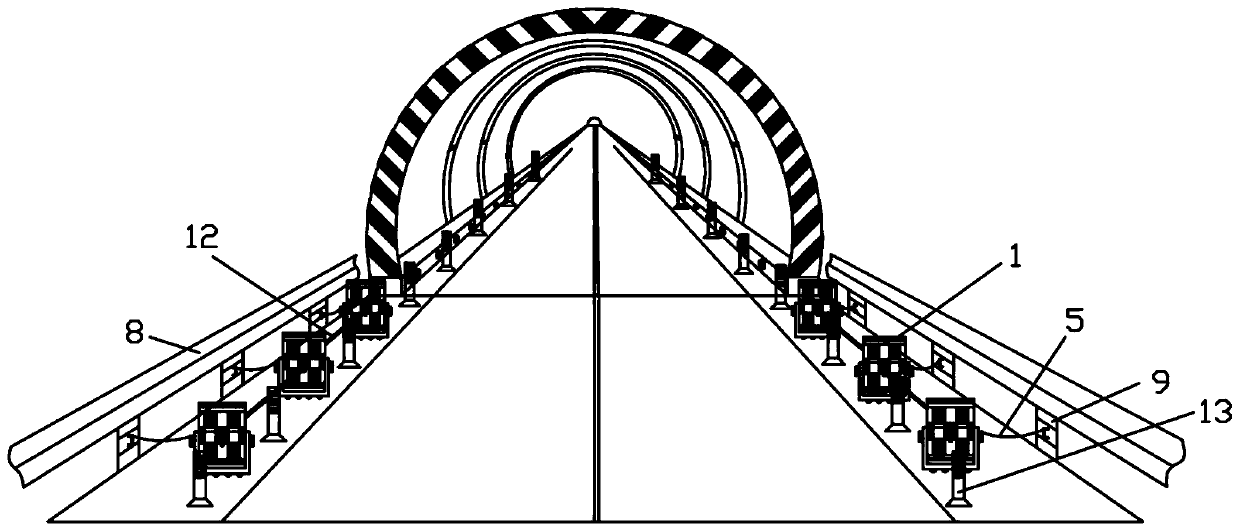
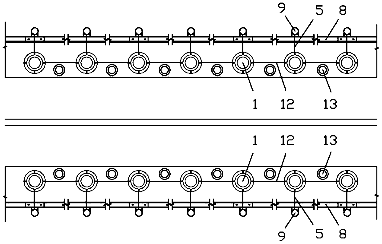
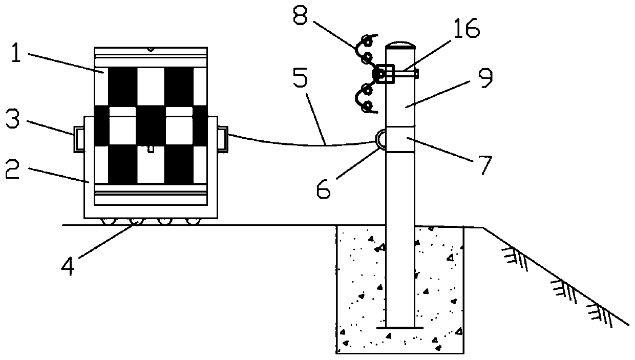
[0037] Such as Figure 1 to Figure 5 As shown, a flexible guardrail structure for the approaching section of a highway tunnel according to the present invention includes a plurality of anti-collision barrels 1, a plurality of guardrail columns 9 and a plurality of warning columns 13 located in the approaching section of the highway tunnel, and a plurality of anti-collision barrels 1 Correspondingly arranged with a plurality of guardrail columns 9, and correspondingly connected by flexible connectors, two adjacent anti-collision barrels 1 are connected by semi-rigid connectors, and two adjacent guardrail columns 9 are connected by rigid connectors Corresponding to the connection, a plurality of warning posts 13 are evenly spaced between the anti-collision bucket 1 and the road sideline. The above constitutes the basic structure of the present invention.

[0038] The present invention adopts such a structural arrangement, and the anti-collision barrel 1 and the guardrail column...

Embodiment 2

[0056] Such as Figure 6 As shown, more specifically, the flexible connector includes a barbed wire 11, and the two ends of the barbed wire 11 are respectively hung on the handle 3 of the anti-collision bucket cover and the handle 6 of the guardrail post cover through the hook 10. Adopting such a structural setting can increase the resistance of the vehicle hitting the roadside object after it deviates from the driving track and enters the roadside, and convert part of the kinetic energy of the vehicle into the internal energy of the anti-collision bucket 1 and the barbed wire 11, which can decelerate the vehicle. function, enhance driving safety, and effectively solve the defects that the existing anti-collision bucket 1 has poor continuity and visibility, and is easily displaced by impact.

[0057] In practical application, the barbed wire 11 is hung on the anti-collision bucket cover handle 3 and the guardrail post cover handle 6 through the hook 10, which is very convenien...


PUM


Abstract

The invention relates to the technical field of traffic safety, in particular to a flexible guardrail structure of a highway tunnel approaching section, and the structure comprises a plurality of anti-collision barrels, a plurality of guardrail upright posts and a plurality of warning posts, wherein the anti-collision barrels, the guardrail upright posts and the warning posts are arranged at the highway tunnel approaching section, the anti-collision barrels and the guardrail upright posts are arranged in a one-to-one correspondence manner and are correspondingly connected through flexible connecting pieces, two adjacent anti-collision barrels are correspondingly connected through semi-rigid connecting pieces, two adjacent guardrail upright posts are correspondingly connected through rigidconnecting pieces, and the warning posts are uniformly arranged between the anti-collision barrels and a road sideline at intervals. By adopting the structure, the problems that the anti-collision barrels are easy to shift due to collision and the integrity and inductivity are poor in the prior art are effectively solved.

Description

technical field [0001] The invention relates to the technical field of traffic safety, in particular to a flexible guardrail structure in the approach section of a highway tunnel. Background technique [0002] The anti-collision bucket is a kind of traffic anti-collision facility, which is widely installed on highways and urban roads where collisions between cars and fixed facilities in the road are likely to occur. Such as: the turning of the road, the entrance and exit of the road and the elevated road, can play the role of isolation warning and collision avoidance. It plays a buffer role in the collision of vehicles, can effectively reduce the impact force, and greatly reduce the damage of vehicles and people. Therefore, vehicle and personnel damage can be significantly reduced. The anti-collision bucket is light in weight and high in strength, strong in corrosion resistance and weather resistance, anti-thawing and moisture-proof (water), strong in overall disposablenes...

Claims


Application Information

Patent Timeline
Patent Type & Authority Applications(China)
IPC IPC(8): E01F15/14E01F9/619E01F9/669E01F9/608
CPCE01F9/608E01F9/619E01F9/669E01F15/14E01F15/146
Inventor 杜志刚何锐王沛源梅家林
Owner WUHAN UNIV OF TECH
Learn More