Novel sprue cup

A sprue cup, a new type of technology, applied in the direction of core, casting mold, casting mold composition, etc., can solve the problems of not meeting large-capacity casting, affecting the quality of castings, destroying the structure of castings, etc., to ensure the quality and performance of castings, and convenient Impurities float up, weakening the effect of scouring

Active Publication Date: 2017-10-03
宁波日星铸业有限公司
View PDF6 Cites 2 Cited by
  • Summary
  • Abstract
  • Description
  • Claims
  • Application Information

AI Technical Summary

Problems solved by technology

[0002] The sprue cup is used to guide the molten metal into the mold. The molten metal will produce a lot of impurities during the smelting process. If the impurities enter the casting, it will damage the structure of the casting and affect the performance of the casting. Generally, the impurities will float in the casting after precipitation. Above the liquid, when the molten metal enters the mold through the gate, it is easy to generate a vortex, and the vortex will bring impurities and air floating on it into the casting, thus affecting the quality of the casting
In addition, many of the existing sprue cups are set up with a single mouth, basically a fixed ladle is used to add liquid, the work efficiency is low, and it cannot meet the needs of large-capacity casting and production.

Method used


Image

  • Novel sprue cup
  • Novel sprue cup
  • Novel sprue cup

Examples


Embodiment Construction

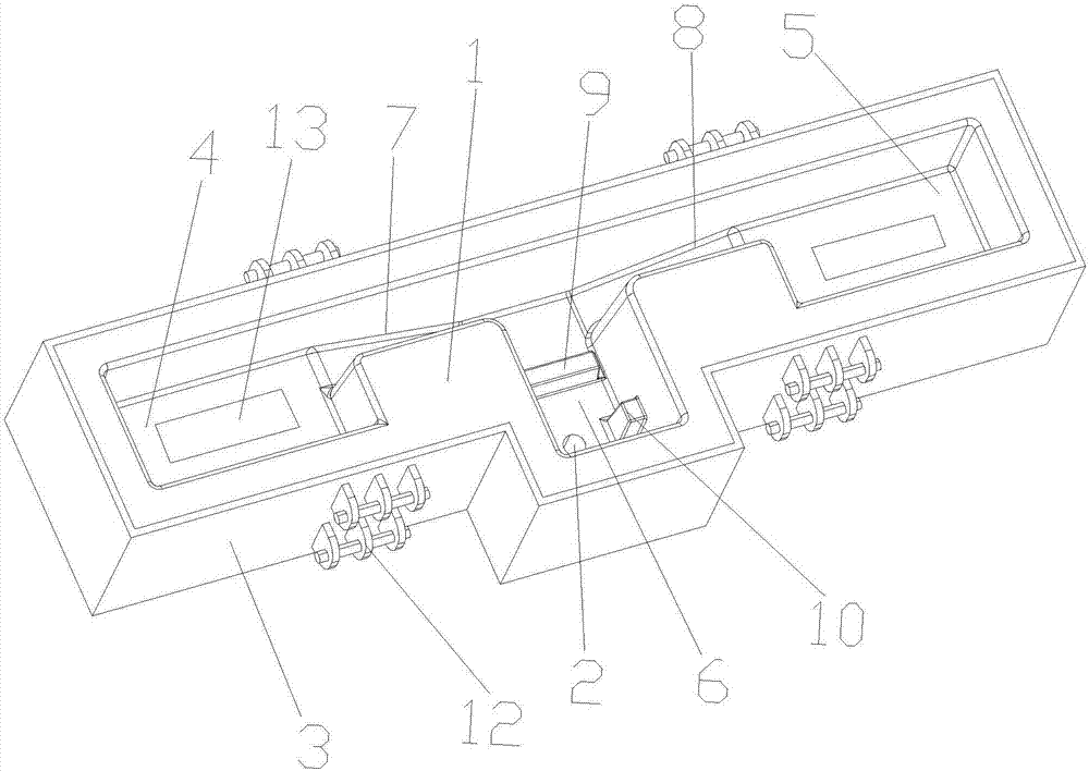
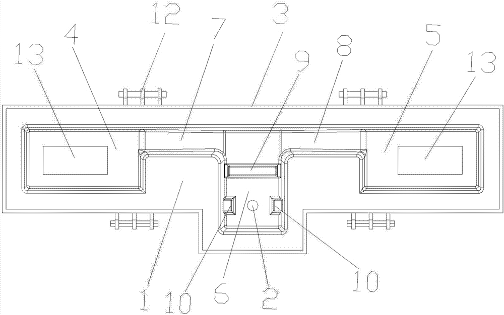
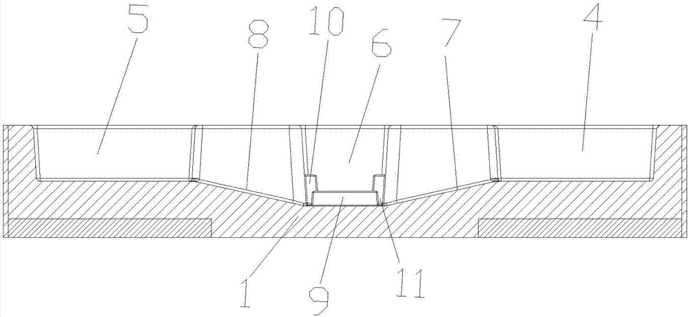
[0019] Such as Figure 1-3 As shown, a new sprue cup includes a body 1, a gate 2, and a sand box 3 wrapped outside the body 1. The outer peripheral wall of the sand box 3 is provided with a hanger 12 for easy hanging. The body 1 includes a symmetrical The provided first pouring chamber 4, the second pouring chamber 5 and the inflow chamber 6 between the first pouring chamber 4 and the second pouring chamber 5, the gap between the first pouring chamber 4 and the inflow chamber 6 There is a first inclined flow channel 7 between them, and a second inclined flow channel 8 is provided between the second pouring cavity 5 and the inflow cavity 6, and the inflow cavity 6 and the first inclined flow channel 7, the second inclined flow channel A cross block 9 is provided at the intersection of the channels 8, and side blocks 10 are provided on both side walls of the inflow chamber 6, and the side blocks 10 are located on both sides of the gate 2 and are on the same straight line as the ...


PUM

PropertyMeasurementUnit
heightaaaaaaaaaa

Abstract

The invention relates to a novel sprue cup. The novel sprue cup comprises a main body, a sprue, and a sand box for wrapping the outer side of the main body; the main body comprises a first pouring cavity and a second pouring cavity symmetrically arranged, and a flowing cavity positioned between the first pouring cavity and the second pouring cavity; a first inclined runner is formed between the first pouring cavity and the flowing cavity; a second inclined runner is formed between the second pouring cavity and the flowing cavity; transverse stoppers are arranged in the intersections of the flowing cavity with the first inclined runner and the second inclined runner; side stoppers are arranged on two side walls of the flowing cavity; and the side stoppers are positioned on two sides of the sprue, and are positioned on the same straight line with the sprue. Two pouring cavities are adopted to satisfy mobile or fixed liquid charging of multiple ladles, so that high-capacity casting of above 30 t can be satisfied, and the working efficiency is improved; and in addition, symmetric side stoppers are arranged on two sides of the sprue for preventing molten metal from forming swirls in the sprue to prevent suction of impurities and air into a casting mold, so that the casting quality and the casting performances are guaranteed.

Description

technical field [0001] The invention relates to the technical field of casting, in particular to a novel sprue cup. Background technique [0002] The sprue cup is used to guide the molten metal into the mold. The molten metal will produce a lot of impurities during the smelting process. If the impurities enter the casting, it will damage the structure of the casting and affect the performance of the casting. Generally, the impurities will float in the casting after precipitation. Above the liquid, when the molten metal enters the mold through the gate, it is easy to generate a vortex, and the vortex will bring impurities and air floating on it into the casting, thereby affecting the quality of the casting. In addition, many of the existing sprue cups are single-ported. In use, a fixed ladle is basically used to add liquid. The work efficiency is low, and it cannot meet the needs of large-capacity casting and production. Contents of the invention [0003] Aiming at the pre...

Claims


Application Information

Patent Timeline
Patent Type & Authority Applications(China)
IPC IPC(8): B22C9/08
CPCB22C9/082
Inventor 何小远赵益锋王惠兵沈光挺
Owner 宁波日星铸业有限公司
Why Eureka
Try Eureka