Hobbing cutter on reverse circulation drilling machine for breaking extremely-hard rock

A reverse circulation, rock technology, applied in the direction of drill bits, drilling equipment, earthwork drilling and mining, etc., can solve the problems of low rock breaking efficiency, unfavorable crack closure, easy wear of the cutter shell, etc., and achieve the effect of improving rock breaking efficiency

Inactive Publication Date: 2019-10-15
CCCC THIRD HARBOR ENG +2
View PDF7 Cites 3 Cited by
  • Summary
  • Abstract
  • Description
  • Claims
  • Application Information

AI Technical Summary

Problems solved by technology

[0005] (1) The area of ​​the main rock-breaking teeth 40 on the hob tool for transmitting force is small, and the shape of the main rock-breaking teeth 40 has no radian, which cannot generate lateral component force, which is not conducive to crack closure, and the rock-breaking efficiency is low;
[0006] (2) The height of the main rock breaking teeth 40 protruding from the surface of the cutter shell on the hob cutter is only 10mm (see figure 1 ), which is less than twice the thickness of the crushed rock, and broken small stones and stone powder are prone to clogging (see figure 2 ) and produce secondary crushing, which is not conducive to the continuous rock breaking of the main rock breaking teeth 40, and the cutter housing 4 is easily worn;
[0007] (3) The compressive strength of the main shaft of the hob cutter is low, ranging from 4t to 8t, and it does not have the ability to transmit a force greater than 1.5 times the compressive strength of the rock
Therefore, the existing hob cutters cannot provide sufficient compressive strength for the crushing of this hard rock

Method used


Image

  • Hobbing cutter on reverse circulation drilling machine for breaking extremely-hard rock
  • Hobbing cutter on reverse circulation drilling machine for breaking extremely-hard rock
  • Hobbing cutter on reverse circulation drilling machine for breaking extremely-hard rock

Examples


Embodiment Construction

[0023] The present invention will be further described below in conjunction with accompanying drawing.

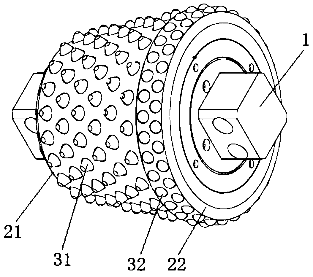
[0024] see Figure 3 to Figure 6 , the hob of the reverse circulation drilling rig used for breaking extremely hard rocks of the present invention includes a main shaft 1, a cutter housing sleeved on the main shaft 1 and rock-breaking teeth installed on the outer surface of the cutter housing.

[0025] The main shaft 1 comprises a circular shaft positioned in the inner chamber of the cutter housing and two sections of square shafts respectively located at the two ends of the circular shaft and protruding from the two end faces of the cutter housing; the middle part of the circular shaft is provided with a flange, and the main side of the flange and A thrust bearing 11 and axle sleeves 12, 13 are respectively arranged in turn on the back side, and a circle of rollers 14, 15 is arranged in each axle sleeve 12, 13, and the outer ends of the two axle sleeves 12, 13 and the roll...


PUM

PropertyMeasurementUnit
Radiusaaaaaaaaaa

Abstract

The invention discloses a hobbing cutter on a reverse circulation drilling machine for breaking extremely-hard rock. A main shaft, a cutter shell and rock breaking teeth are included. The cutter shellcomprises a main cutter shell and a back cutter shell which are adjacent. The rock breaking teeth comprise main teeth arranged on the main cutter shell and back teeth arranged on the back cutter shell. The height that a main tooth head of each main tooth protrudes out of the periphery face of the main cutter shell is 12.5-15 mm, the bottom radius of each main tooth head is 18-20 mm, the top faceof each main tooth head is a ball cambered surface with the radius being 5-6 mm, and the side face of each main tooth head is a ball cambered surface with the radius being 20-30 mm, wherein the ball cambered surface with the radius being 20-30 mm is in smooth connection with the top face. The back teeth are embedded in two circles of back tooth holes formed in the periphery face of the back cuttershell, the distance between the two circles of back tooth holes is 15-20 mm, and the two circles of back tooth holes are arranged in a staggered manner. The back tooth root of each back tooth is a cylinder, and the tooth head of each back tooth is a hemisphere. By means of the hobbing cutter, when the drilling machine applies the acting force which is 1.5-3 times of the rock comprehensive strength, the rock with the compressive strength larger than 160 MPa can be broken.

Description

technical field [0001] The invention relates to a hob on a reverse circulation drilling rig used for breaking extremely hard rocks, mainly used for drilling extremely hard rocks whose compressive strength is greater than 160MPa. Background technique [0002] In the construction of rock-socketed foundation of steel pipe piles for high pile caps in offshore wind farms, it is necessary to drill through moderately and slightly weathered rocks for rock-socketed drilling construction. The compressive strength of the medium and slightly weathered rocks traversed is concentrated at 120-150MPa, which belongs to hard rock , the integrity of the rock mass is good, and the existing large-diameter reverse circulation rock-socketed drilling rig variable-diameter drill bit tool is used for rock-socketed drilling footage and hard rock breaking efficiency is low, and during the drilling process, the hob High degree of wear and low service life. [0003] At present, when the raise drilling r...

Claims


Application Information

Patent Timeline
IPC IPC(8): E21B10/43E21B10/46
CPCE21B10/43E21B10/46
Inventor 郭新杰熊汉东方蔚徐家霆林晓廖玉珍
Owner CCCC THIRD HARBOR ENG
Why Eureka
Try Eureka