Light guide plate and manufacturing method thereof

A manufacturing method and technology of a light guide plate, applied in the field of light guide, can solve the problems of light waste and low light utilization rate, and achieve the effect of improving utilization rate, reducing bright clusters or dark shadows, and uniform light output

Inactive Publication Date: 2019-10-15
DONGGUAN YUANLI ELECTRONICS TECH
View PDF7 Cites 2 Cited by
  • Summary
  • Abstract
  • Description
  • Claims
  • Application Information

AI Technical Summary

Problems solved by technology

[0003] Among them, the light guide plate can diverge the incident light from the light-emitting surface in all directions. When the light guide plate is applied on the display screen of mobile phone, tablet or industrial control, etc., the user generally observes and operates in the direction of the front viewing angle of the display screen, which leads to The light emitted by the light panel beyond the normal viewing angle is greatly wasted, and the light utilization rate is not high

Method used


Image

  • Light guide plate and manufacturing method thereof
  • Light guide plate and manufacturing method thereof
  • Light guide plate and manufacturing method thereof

Examples


Embodiment Construction

[0031] The following will clearly and completely describe the technical solutions in the embodiments of the present invention with reference to the drawings in the embodiments of the present invention. It should be noted that if there is a directional indication (such as up, down, left, right, front, back...) in the embodiment of the present invention, the directional indication is only used to explain the position in a certain posture (as shown in the accompanying drawing). If the specific posture changes, the directional indication will also change accordingly. In addition, if there are descriptions involving "first", "second" and so on in the embodiments of the present invention, the descriptions of "first", "second" and so on are only for descriptive purposes, and should not be interpreted as indicating or implying Its relative importance or implicitly indicates the number of technical features indicated. Thus, the features defined as "first" and "second" may explicitly o...


PUM


Abstract

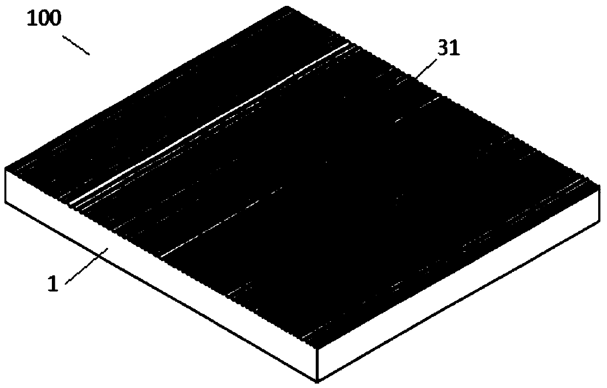
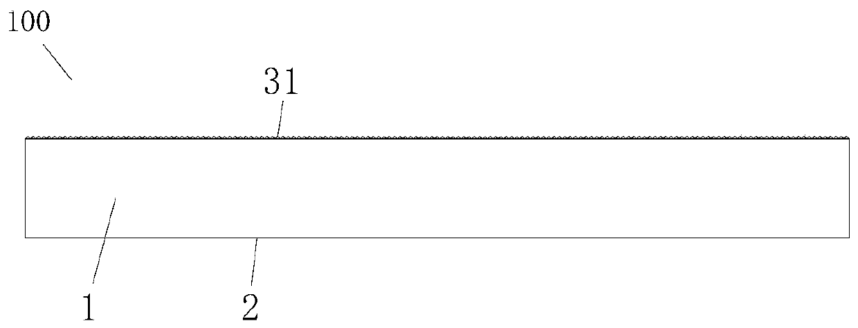
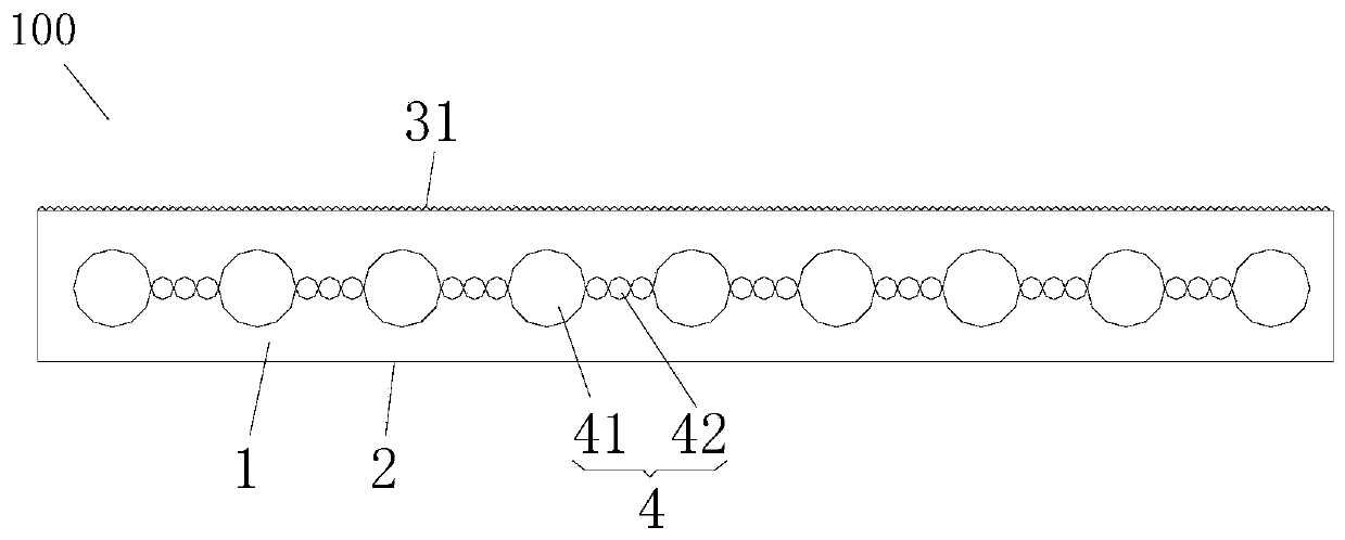
The present invention relates to the field of light guide technologies, and relates to a light guide plate and a manufacturing method thereof. The light guide plate comprises an in-light surface, an out-light surface, and a reflecting surface. The out-light surface has a hairline holographic structure, wherein the hairline holographic structure is of a drawn wire structure. Surface roughness Ra ofthe out-light surface is 0.005-0.02 mm. According to the technical solutions provided in the present invention, the hairline holographic structure is disposed on the out-light surface, and a hairlineholographic depth is limited by using the surface roughness of the out-light surface. In this way, a light exiting angle can be changed, so that light intensively exits within a range of zero-degreepositive viewing angle, thereby improving a light use ratio of an effective light emitting area, and reducing light divergence in an invalid direction. The hairline holographic structure is set to bean irregular drawn wire structure, so that light may be further enabled to scatter into various different directions within the positive viewing angle, thereby reducing a local brightness/shadow phenomenon on the out-light surface. Therefore, light exits more evenly, so that visual experience is softer.

Description

technical field [0001] The invention relates to the field of light guide technology, in particular to a light guide plate and a manufacturing method thereof. Background technique [0002] The light guide plate is made of optical grade PMMA / PC material and optical texture microstructure integrated injection molding. Specifically, the light guide plate has a light incident surface, a reflective surface and a light output surface. The light enters the inside of the light guide plate from the light incident surface, the light propagates inside the light guide plate, passes through the light texture microstructure to make the light diffusely reflected, and then the light is emitted from the light exit surface of the light guide plate. [0003] Among them, the light guide plate can diverge the incident light from the light-emitting surface in all directions. When the light guide plate is applied on the display screen of mobile phone, tablet or industrial control, etc., the user g...

Claims


Application Information

Patent Timeline
Patent Type & Authority Applications(China)
IPC IPC(8): G02B6/00
CPCG02B6/0016G02B6/0038G02B6/0065
Inventor 黄爱群阮绪红
Owner DONGGUAN YUANLI ELECTRONICS TECH
Why Eureka
Try Eureka