Crop transplanter

A technology for transplanting machines and crops, applied in the field of transplanting machines, can solve the problems of manual seedling separation, low degree of automation, poor work efficiency, etc., and achieve the effects of improving work efficiency, reducing manual operations, and increasing practicability

Inactive Publication Date: 2019-10-18
肥东县爱雯家庭农场
0 Cites 10 Cited by

AI-Extracted Technical Summary

Problems solved by technology

[0006] The object of the present invention is to provide a kind of crop transplanting machine, to solve the problem that the existing crop transplanting machines proposed in the above-mentioned background technology almost all need artificial seedling separation and seedling removal, cannot aut...

Abstract

The invention discloses a crop transplanter which comprises a mounting frame, a feeding seat, a blanking mechanism, a rack and a driving mechanism. The driving mechanism is fixed to the center of thetop of the rack, second electric push rods and supports are uniformly mounted at two ends of the driving mechanism respectively, two seedling frames are uniformly hinged to the upper portion between the two supports, and a control handle seat is mounted at one end of the rack. The blanking mechanism is fixed between the control handle seat and the supports, and a feeding seat is arranged above theblanking mechanism. By installing a second motor and material guiding discs, the four material guiding discs are convenient to rotate through the rotation of the second motor, when a groove in the first material guiding disc enters the corresponding gap in a seedling tray, the grooves of the remaining three material guiding discs enter the corresponding gaps in the seedling tray in sequence, cropseedlings in the seedling tray fall at intervals in sequence, the crop seedlings are convenient to automatically drop one by one, the manual operation is reduced, the cost is reduced, and the workingefficiency is improved.

Application Domain

Technology Topic

Image

  • Crop transplanter
  • Crop transplanter
  • Crop transplanter

Examples

  • Experimental program(1)

Example Embodiment

[0020] The technical solutions in the embodiments of the present invention will be clearly and completely described below in conjunction with the accompanying drawings in the embodiments of the present invention. Obviously, the described embodiments are only a part of the embodiments of the present invention, rather than all the embodiments. Based on the embodiments of the present invention, all other embodiments obtained by those of ordinary skill in the art without creative work shall fall within the protection scope of the present invention.
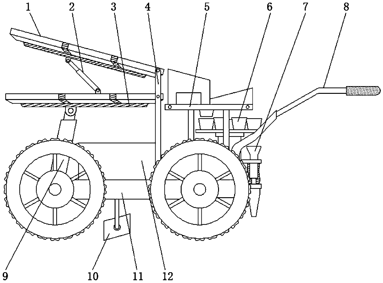
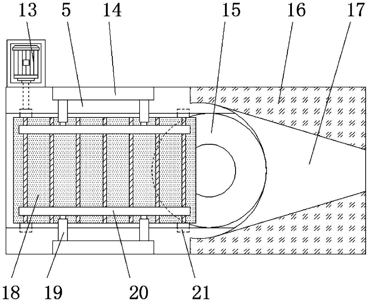
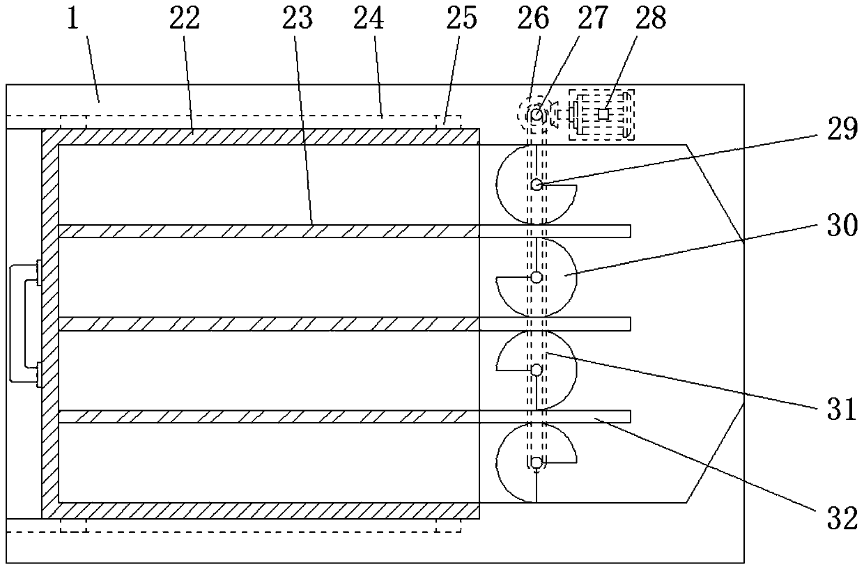
[0021] See Figure 1-3 , An embodiment provided by the present invention: a crop transplanting machine, including a mounting frame 3, a feeding seat 5, a feeding mechanism 6, a frame 11 and a driving mechanism 12, both sides of the frame 11 are evenly installed with wheels , The bottom of the frame 11 between the two adjacent wheels is connected with the soil shovel 10, and the center of the top of the frame 11 is fixed with a driving mechanism 12, and the two sides of the frame 11 at both ends of the driving mechanism 12 are evenly installed with second Electric push rod 9 and bracket 4, and the upper part between the two brackets 4 is evenly hinged with 2 seedling racks 1. Both sides of one end of the seedling rack 1 are provided with chutes 24, and the inside of the seedling rack 1 between the chutes 24 The seedling tray 22 is slidably connected to the seedling tray 22. Both sides of the seedling tray 22 are evenly fixed with sliders 25. The sliders 25 are slidably connected to the chute 24 on the same side, and the inside of the seedling tray 22 is evenly connected with a baffle 23. The inner part of the frame 1 far away from the seedling tray 22 is uniformly provided with partitions 32, and the partitions 32 are on the same horizontal line as the adjacent baffles 23, and 4 rotating shafts are vertically inserted inside the seedling frame 1 on the side of the partition 32 29. The outer side of the bottom of the rotating shaft 29 is provided with a rack, a transmission shaft 27 is vertically inserted into the inner wall of one side of the seedling frame 1, a trapezoidal gear 26 is fixed at the center of the outer side of the transmission shaft 27, and the transmission shaft 27 and 4 rotating shafts 29 There is a transmission chain 31 between them. The transmission chain 31 is respectively connected to the trapezoidal gear 26 and the rack. The rotating shaft 29 is equipped with a guide plate 30. The guide plate 30 is provided with grooves and the size of the grooves Equal to 1/3 of the guide plate 30, the second, third, and fourth grooves respectively correspond to the state after the first groove is rotated by 90°, 180° and 270°. The inner wall of the seedling frame 1 at one end of the drive shaft 27 The second motor 28 is fixed, and the output end of the second motor 28 is equipped with connecting gears, and the connecting gears are all toothed and connected with the trapezoidal gears 26. The bottom of the seedling frame 1 is equipped with a mounting frame 3, and the seedling frame 1 below Both sides of the top are hinged with the first electric push rod 2, and the output end of the first electric push rod 2 is hingedly fixed with the bottom end of the upper mounting frame 3, and both ends of the bottom of the lower mounting frame 3 are connected with the second The output ends of the two electric push rods 9 are hinged and fixed, and the frame 11 is mounted with a control handle base 8 at one end away from the second electric push rod 9, one end of the control handle base 8 is equipped with a non-slip sleeve, and one end of the seedling tray 22 is connected with The grip is convenient to increase the anti-slip property of the control handle base 8, avoiding slipping between the palm and the device when the user grasps the control handle base 8 to move the device, and facilitates the user's control of the device and facilitates the user to pass the grip The seedling tray 22 is grasped and pulled to facilitate the disassembly and replacement of the seedling tray 22 and the addition of crop seedlings. The top of the frame 11 between the control handle base 8 and the bracket 4 is fixed with a feeding mechanism 6 and a feeding mechanism 6 A seedling insertion mechanism 7 is fixed at one end of the lower frame 11, and the wheels, the feeding mechanism 6 and the seedling insertion mechanism 7 are all connected with the driving mechanism 12, and a feeding seat 5 is installed above the feeding mechanism 6 through a support frame, and the feeding seat A first motor 13 is fixed at one end of the first motor 13, a cavity is provided in the center of the feeding base 5 at one end of the first motor, and two drive shafts 21 are inserted transversely through one end of the cavity, and the first motor The side of the drive shaft 21 at one end of the motor 13 is fixedly connected to the output end of the first motor 13. A conveyor belt 18 is fitted between the two drive shafts 21. The conveyor belt 18 is evenly provided with ribs, which facilitates the increase of the surface of the conveyor belt 18 through the ribs. The friction of the crop seedlings prevents the crop seedlings from sticking to the surface of the conveyor belt 18 when transported on the conveyor belt 18, which facilitates the transmission of the crop seedlings. The top of the feeding base 5 on both sides of the conveyor belt 18 is fixed with a first fixing seat 14, the first fixing The third electric push rod 19 is evenly fixed on one side of the seat 14, and the output ends of two adjacent third electric push rods 19 are connected with a seedling baffle 20, and the feeding seat 5 is installed away from the top of one end of the conveyor belt 18. There is a seedling guide seat 16, both the seedling guide seat 16 and the seedling blocking plate 20 are set as trapezoidal plates, and the long plate ends of the trapezoidal plates are set at both ends of the feeding base 5, and the short plate ends of the trapezoidal plates are all set at the feeding base 5. In the middle part, a rubber gasket is fixed on one side of the seedling baffle 20, which facilitates the effective guidance of crop seedlings through the seedling guide seat 16 of the trapezoidal structure, and facilitates the direction of the root end of the crop seedlings transported on the conveyor belt 18 and the transmission direction of the conveyor belt 18. In a short while, the crop seedling branches and leaves that preferentially reach one end of the seedling guide seat 16 move along the seedling guide seat 16, until the root end of the crop seedling reaches the end of the conveyor belt 18 and automatically fall under the action of gravity, thereby effectively ensuring that the root end of the crop seedling is always at the bottom , Ensure that the root end of crop seedlings is fully inserted into the soil, avoid the phenomenon that the roots of crop seedlings can not be fully inserted into the soil during the transplanting process, effectively ensure the survival rate of crop seedlings, and facilitate the trapezoidal structure of the seedling block 20 to block the seedling rack 1. The crop seedlings falling on the top can prevent the crop seedlings from falling when they fall on the feeding base 5. At the same time, it is convenient to increase the elasticity of the baffle plate 20 through the rubber gasket, and prevent the crop seedlings from being squeezed and deformed between the baffle plates 20 And damage to ensure the integrity of crop seedlings, the center of the seedling guide seat 16 is provided with a guide groove 17, and the center of the bottom of the feeding seat 5 between the guide groove 17 and the conveyor belt 18 is connected with a lower hopper 15, and the top of the lower hopper 15 and The cavities are connected, the guide groove 17 is set as an oblique trapezoidal groove, the guide groove 17 is inclined to one end of the lower hopper 15, and the diameter of the top of the lower hopper 15 is equal to the width of the cavity, and the diameter of the bottom of the lower hopper 15 is smaller than that of the feeding mechanism 6 The diameter of the upper end of the tube is convenient for the crop seedlings to be transported on the conveyor belt 18. The direction of the root end of the crop seedlings and the conveying direction are different. The crop seedling branches and leaves that first reach the end of the seedling guide seat 16 move along the inclined guide groove 17 until the root end of the crop seedlings reaches the conveyor belt 18. After the end, it will automatically fall under the action of gravity to ensure that the root end of the crop seedling will always remain at the bottom when it falls into the lower hopper 15, so as to ensure that the root end of the crop seedling is fully inserted into the soil, and ensure that the branch and leaf end of the crop seedling is above the soil to prevent the crop seedling from falling The phenomenon that the roots cannot be fully inserted into the soil during the transplanting process.
[0022] Working principle: Before use, put the crop seedlings into the seedling tray 22 in the seedling rack 1, so that the number of crop seedlings between each gap in the seedling tray 22 on both sides of the baffle plate 23 is equal. When in use, the driving mechanism 12 The oil tank provides the power source for the device, so that the user holds the control handle base 8 to push the device to move and work, so that the first motor 13 and the second motor 28 work, and the first electric push rod 2 and the third electric push rod The expansion and contraction 19 makes the first electric push rod 2 drive the upper seedling rack 1 to tilt toward one end of the support 4, so that the third electric push rod expansion and contraction 19 drives the seedling block 20 to move, so that the spacing between the seedling blocks 20 is slightly larger than the size of crop seedlings, At this time, the second motor 28 drives the connecting gear at the output end to rotate, and the trapezoidal gear 26 is engaged to drive the transmission shaft 27 to rotate, so that the transmission chain 31 drives the four rotating shafts 29 and the four guide plates 30 to rotate. When the first guide plate 30 is on When the grooves in the seedling tray 22 enter the corresponding gaps in the seedling tray 22, the grooves of the remaining three guide trays 30 are about to enter the corresponding gaps in the seedling tray 22 in sequence, so that the crop seedlings in the seedling tray 22 will fall at intervals, and the fallen crop seedlings will fall. Enter the conveyor belt 18 between the seedling baffle plates 20, and transmit through the electric conveyor belt 18 of the first motor 13 and the end of the crop seedling guide seedling seat 16. When the direction of the root end of the crop seedlings transported on the conveyor belt 18 is consistent with the transmission direction of the conveyor belt 18, The root end of the crop seedlings reaches the end of the conveyor belt 18 preferentially. Because the root end of the crop seedlings is heavier than the branches and leaves of the crop seedlings, the gravitational force at the root end of the crop seedlings falls into the top of the lower hopper 15 in the cavity, and the lower hopper 15 feeds the cutting material In the mechanism 6, the seedling insertion mechanism 7 is inserted into the soil to complete the transplantation. When the root end of the crop seedlings transported on the conveyor belt 18 is different from the transmission direction of the conveyor belt 18, the leaf ends of the crop seedlings that reach one end of the seedling guide seat 16 are suspended in the air. The seedling guide seat 16 moves upward along the inclined guide groove 17 until the root end of the crop seedling reaches the end of the conveyor belt 18 and then automatically falls under the action of gravity, thereby effectively ensuring that the root end of the crop seedling falling into the lower hopper 15 is always at At the bottom, ensure that the roots of crop seedlings are fully inserted into the soil to prevent the crop seedlings from turning over during the process of falling into the cutting mechanism 6, avoid the phenomenon that the roots of the crop seedlings inserted by the seedling mechanism 7 cannot be fully inserted into the soil, and effectively ensure that the crop seedlings The survival rate of the traditional transplanter is effectively improved, and the manual feeding and unloading operation of the traditional transplanting machine is effectively improved, and the work efficiency is improved.
[0023] For those skilled in the art, it is obvious that the present invention is not limited to the details of the foregoing exemplary embodiments, and the present invention can be implemented in other specific forms without departing from the spirit or basic characteristics of the present invention. Therefore, from any point of view, the embodiments should be regarded as exemplary and non-limiting. The scope of the present invention is defined by the appended claims rather than the above description, and therefore it is intended to fall within the claims. All changes within the meaning and scope of equivalent elements of are included in the present invention. Any reference signs in the claims should not be regarded as limiting the claims involved.

PUM

no PUM

Description & Claims & Application Information

We can also present the details of the Description, Claims and Application information to help users get a comprehensive understanding of the technical details of the patent, such as background art, summary of invention, brief description of drawings, description of embodiments, and other original content. On the other hand, users can also determine the specific scope of protection of the technology through the list of claims; as well as understand the changes in the life cycle of the technology with the presentation of the patent timeline. Login to view more.

Similar technology patents

Optical device

Owner:SUMITOMO ELECTRIC IND LTD

Classification and recommendation of technical efficacy words

  • Improve practicality
  • Reduce manual operations
Why Eureka
Try Eureka