Eureka AIR delivers breakthrough ideas for toughest innovation challenges, trusted by R&D personnel around the world.

Anoscope and using method thereof

The technology of an anoscope and lens barrel, which is applied in the field of anoscope, can solve the problems of not considering the pollution of the lubricating fluid, not cleaning the lubricating fluid in time, and having a small lubricating effect, so as to achieve the advantages of simple structure, avoiding overdrying, and reducing friction Effect

Active Publication Date: 2019-10-18
黄毅然
View PDF14 Cites 4 Cited by
  • Summary
  • Abstract
  • Description
  • Claims
  • Application Information

AI Technical Summary

Problems solved by technology

However, this solution still has the following problems: when inserting the lens core into the anus, the interior of the anus is not smooth enough, and when the lens tube is inserted into the interior, it may be too dry and the friction force is too large, causing damage to the anus
Although this solution takes into account the fact that the inside of the anus is not smooth enough and the insertion may cause damage to the anus, it uses the outlet hole on the top of the inner core to discharge the lubricating fluid. In the case of adding lubricating fluid through the outlet hole, a large part of the lubricating fluid enters Into the anus and into the end of the rectum, the lubricating effect is small, which affects the observation, and does not take into account the pollution caused by the outflow of the lubricating fluid, that is, the lubricating fluid flowing out during the operation is not cleaned up in time

Method used


Image

  • Anoscope and using method thereof
  • Anoscope and using method thereof
  • Anoscope and using method thereof

Examples


Embodiment Construction

[0033] The technical solutions in the embodiments of the present invention will be clearly and completely described below in conjunction with the accompanying drawings in the embodiments of the present invention. Obviously, the described embodiments are only a part of the embodiments of the present invention, rather than all the embodiments. Based on the embodiments of the present invention, all other embodiments obtained by those of ordinary skill in the art without creative work shall fall within the protection scope of the present invention.

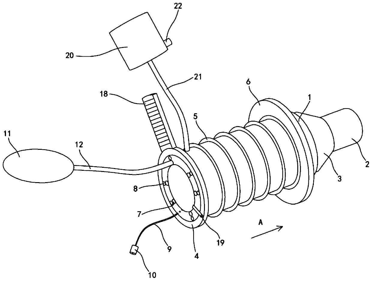
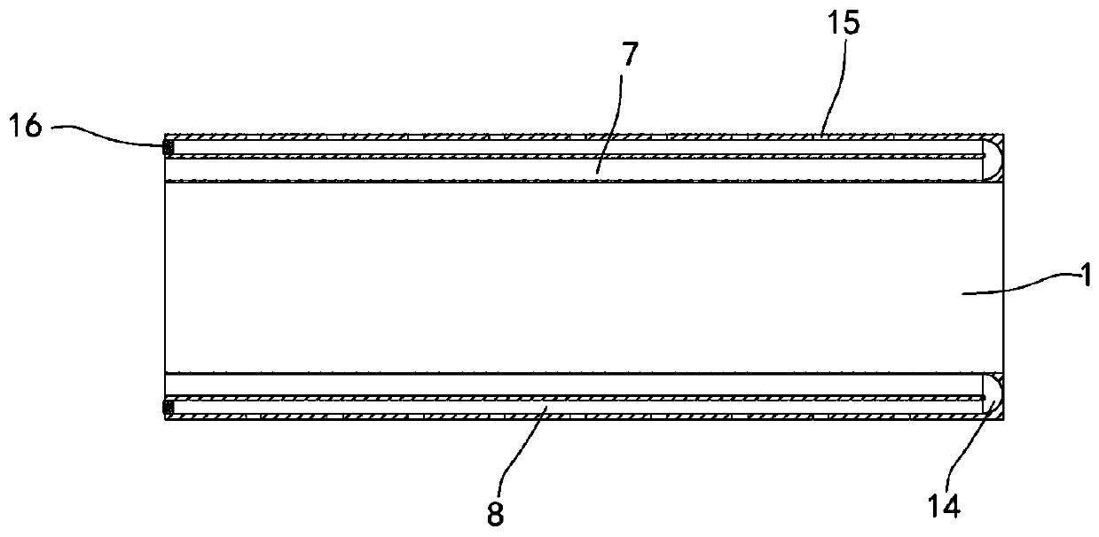
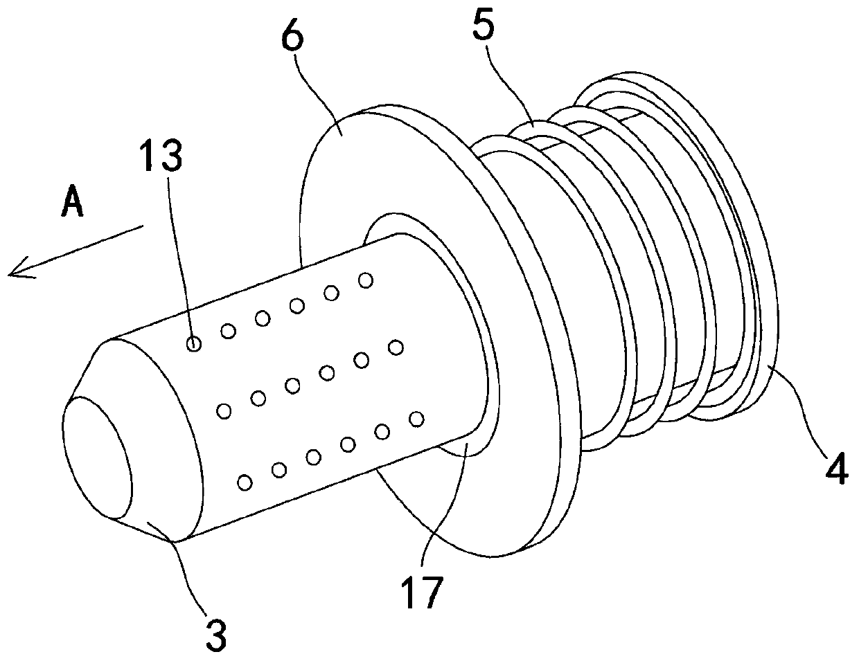
[0034] See Figure 1~6 , The present invention provides a technical solution:

[0035] An anoscope, including a lens barrel 1, a lens core 2, a rubber liquid storage bag 11, and a micro water pump 20, for ease of description figure 1 , 3 5. In 5, the direction A is the head end, and the opposite direction is the tail end. The head end of the lens barrel 1 has a truncated cone-shaped cylinder 3 integrally connected or separated, and the len...


PUM


Abstract

The invention relates to the technical field of medical apparatuses, in particular to an anoscope and a using method thereof. The anoscope comprises an anoscope cylinder, an anoscope core, a rubber liquid storage bag and a miniature water pump, the head end of the anoscope cylinder is provided with a circular-truncated-cone-shaped cylinder which is in integrated connection or split connection, andthe anoscope core is inserted into the tail end of the anoscope cylinder and exposed after penetrating through the circular-truncated-cone-shaped cylinder; the tail end of an elastic corrugated sleeve is hermetically fixed to the tail end of the anoscope cylinder, the head end of the elastic corrugated sleeve is provided with a circular cover, and several liquid infusion channels and liquid outlet channels are formed in the cylinder wall in the axial direction of the tail end of the anoscope cylinder; the tail ends of the liquid outlet channels are sealed, the head ends of the liquid infusionchannels and the liquid outlet channels are connected through a pipe I, a rubber liquid storage bag is connected with the tail ends of the liquid infusion channels through a pipe II, liquid outlet holes communicated with the liquid outlet channels are formed in the anoscope cylinder, and the miniature water pump is connected with a storage cavity through a pipe IV. The anoscope is simple in structure, capable of being repeatedly cleaned for use, and high in operation efficiency, leakage is avoided, and contamination and internal anal injuries cannot be caused.

Description

Technical field [0001] The invention relates to the technical field of medical devices, in particular to an anoscope and a method of use thereof. Background technique [0002] At present, the known anoscope structure is mainly composed of a mirror tube and an inner core. The inner core is cylindrical and the head has protrusions. The outer diameter of the inner core is (slightly) smaller than the inner diameter of the mirror tube, so the inner core can just fit into the lens tube. In the middle, the convex part at the front end of the inner core just protrudes out of the mirror tube. In anorectal surgery, the surgeon inserts an anoscope with an inner core into the anus, and then fixes the mirror tube by suture the edge of the mirror on the perianal skin, and the mirror tube can open the anal sphincter that composes the anal canal. At this time, the inner core is pulled out, and the deep tissue of the anal canal can be seen through the mirror tube, which is convenient for the ope...

Claims


Application Information

Patent Timeline
IPC IPC(8): A61B1/31A61B1/07A61B1/012
CPCA61B1/012A61B1/07A61B1/31
Inventor 朱世新
Owner 黄毅然
Why Eureka
Eureka Blog
Learn More