Recycling glycol stirring and mixing tank

A technology of stirring and mixing, ethylene glycol, applied in the direction of chemical instruments and methods, chemical/physical processes, feeding devices, etc., can solve problems such as mutual interference, easy blockage of pipes and flowmeters, uneven distribution, etc., to prevent inhalation Exhaust system, reduce the loss of ethylene glycol, improve the effect of stability

Inactive Publication Date: 2019-10-18
TONGKUN GRP
View PDF7 Cites 0 Cited by
  • Summary
  • Abstract
  • Description
  • Claims
  • Application Information

AI Technical Summary

Problems solved by technology

[0003] But at present, the internal structure of the recycling ethylene glycol tank of almost all polyester plants with one end and multiple tails is not specially designed, and its structure is as follows: figure 2 As shown, it is just a container such as a tank, the top of the tank is connected to the polycondensation glycol recycling pipeline, and there is an exhaust gas recovery outlet on the top of the tank, and the flow meter valve group and the regulating valve valve group are connected to the bottom of the tank , the slurry is transported to the slurry tank through the pipeline, without considering that the content of various entrained substances in the recycled ethylene glycol is not the same, it has the following disadvantages: 1. It is only a static container, and ethylene glycol is reused in each way Alcohol enters from the top of the tank without sufficient mixing and uneven distribution; 2. Recycled ethylene glycol contains more unreacted small molecule polymers, which are prone to sedimentation at the bottom of the tank. With the extension of the production cycle , the stock is accumulating more and more, once there is a disturbance, it is easy to block the pipeline and flowmeter, and in severe cases, it will also affect the stability of production and the dyeing of the product; 3. In order to avoid the mutual interference between the various lines, some devices are also designed In order to reuse the ethylene glycol refining device, this device not only consumes a lot of energy, but also produces a large amount of solid waste

Method used


Image

  • Recycling glycol stirring and mixing tank
  • Recycling glycol stirring and mixing tank

Examples


Embodiment Construction

[0015] The present invention will be further described below in conjunction with accompanying drawing and specific embodiment:

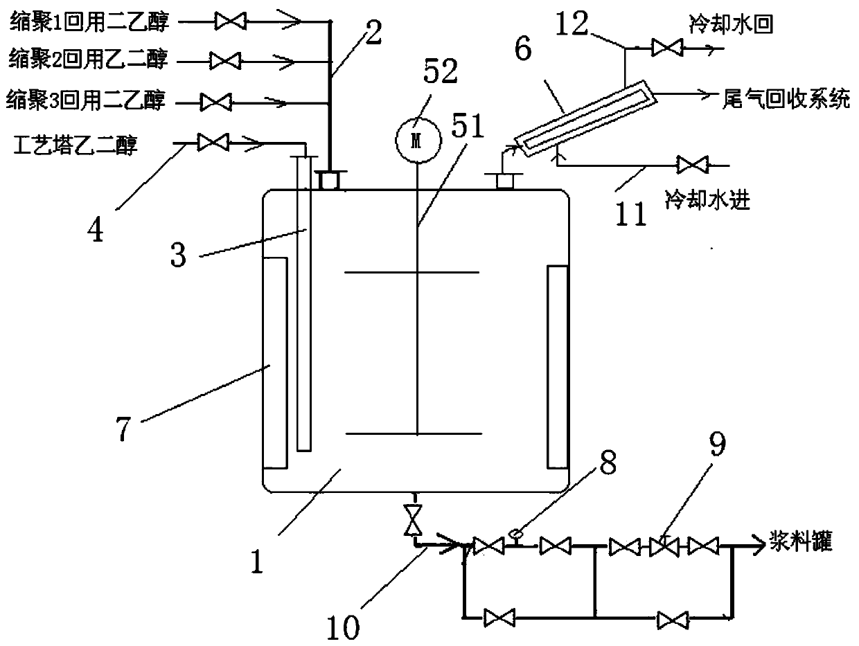
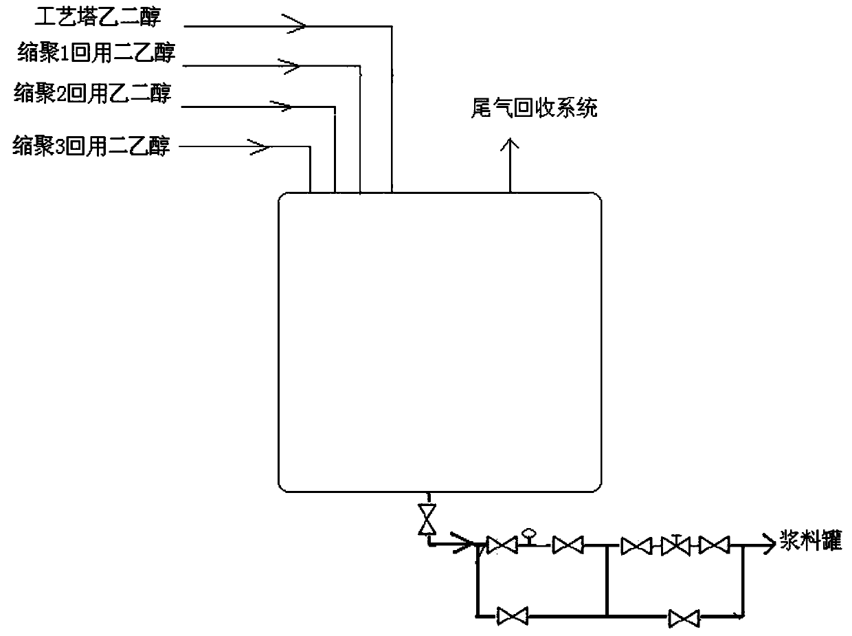
[0016] Such as figure 1 As shown, a mixing tank for recycling ethylene glycol includes a mixing tank body 1, a liquid inlet is provided on the top of the tank body 1, and the liquid inlet is connected to the polycondensation recycling ethylene glycol pipeline 2, and also includes a submerged intubation tube 3. The top of the sinking intubation 3 is connected to the high-temperature ethylene glycol pipeline 4 coming out of the process tower. The lower end of the sinking intubation 3 penetrates the tank body and extends below the diethanol liquid level, and seals the penetration. Preferably, the sinking Cannula 3 is vertically arranged, and its lower end is 40cm away from the bottom of the tank. The tank body 1 is also provided with a stirring device and a jacket condenser 6. The stirring device includes a stirring shaft 51 extending into the tank an...


PUM


Abstract

The invention discloses a recycling glycol stirring and mixing tank. The recycling glycol stirring and mixing tank comprises a tank body, a liquid inlet is formed in the tank body, the liquid inlet isconnected with a polycondensation recycling glycol pipeline; and further comprises a sinking and inserting pipe, the top end of the sinking and inserting pipe is connected with high temperature glycol pipeline coming from a process tower, the lower end of the sinking and inserting pipe penetrates through the tank body and extends to the lower part of a liquid level, and the tank body is also provided with a mixing device and a jacket condenser. According to the recycling glycol stirring and mixing tank, the original static storage mode of recycling glycol is changed, the loss of glycol is reduced, the flash vaporization phenomenon caused by the direct top entry of high temperature glycol is avoided, material mixing is even, and discharge pipeline blocking under long-term working conditions is avoided.

Description

Technical field: [0001] The invention relates to the field of chemical industry, in particular to a stirring and mixing tank for recycled ethylene glycol. Background technique: [0002] In the PET polyester production process, most of the recycled ethylene glycol produced in the polycondensation section and the ethylene glycol extraction system in the process tower is recycled into the mixed ethylene glycol tank before being used for slurry preparation. With the continuous advancement of polyester technology, the popularization speed of the device with one head and two tails and one head and three tails is relatively fast. It has the characteristics of low energy consumption, product differentiation and diversification. It is precisely because of these characteristics that the differentiated poly In the ester plant, due to different products and different yields, the contents of diethylene glycol, unreacted small molecules or three monomers contained in recycled ethylene gly...

Claims


Application Information

Patent Timeline
Patent Type & Authority Applications(China)
IPC IPC(8): B01J4/02B01J4/00
CPCB01J4/02B01J4/008B01J4/001B01J2204/002B01J2204/007
Inventor 沈良华徐汉杰朱伟锴肖顺立杨文虎张桂萍
Owner TONGKUN GRP
Why Eureka
Try Eureka