
Spark assisted chemical engraving technology of tool electrode end multiple-corner discharge constraint

A tool electrode, discharge restraint technology, applied in electric processing equipment, manufacturing tools, metal processing equipment and other directions, can solve the problems of easy failure of the insulating layer, high cost, low cost, etc.

Active Publication Date: 2019-10-18
TSINGHUA UNIV
View PDF6 Cites 0 Cited by
  • Summary
  • Abstract
  • Description
  • Claims
  • Application Information

AI Technical Summary

Problems solved by technology

This method is suitable for micro-electrodes of various shapes, and the insulating layer is thin enough for deep hole processing; but the cost is expensive, and the insulating layer is prone to failure in discharge-assisted chemical processing; (3) micro-drilling electrode: using a micro-drill as a tool The electrode, through the rotation of the motor, can promote the renewal of the electrolyte at the end of the electrode
This method is low in cost and can effectively improve the renewal of the electrolyte at the tip of the tool electrode; however, it cannot achieve the discharge constraint at the tip of the tool electrode
Therefore, there is still a lack of a low-cost, durable SACE processing technology that can effectively restrain the discharge at the end of the tool electrode and better achieve electrolyte renewal.

Method used


Image

  • Spark assisted chemical engraving technology of tool electrode end multiple-corner discharge constraint
  • Spark assisted chemical engraving technology of tool electrode end multiple-corner discharge constraint
  • Spark assisted chemical engraving technology of tool electrode end multiple-corner discharge constraint

Examples


Embodiment Construction

[0026] Embodiments of the present invention are described in detail below, examples of which are shown in the drawings, wherein the same or similar reference numerals designate the same or similar elements or elements having the same or similar functions throughout. The embodiments described below by referring to the figures are exemplary and are intended to explain the present invention and should not be construed as limiting the present invention.

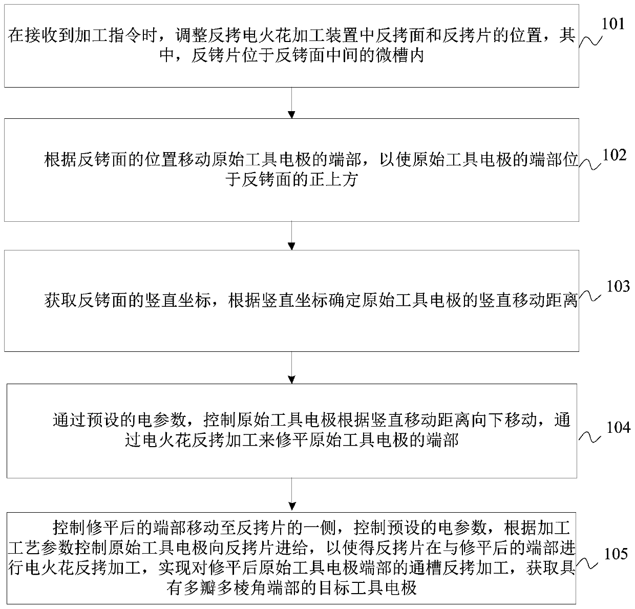
[0027] The method and device for discharge-assisted chemical machining based on tool electrodes according to the embodiments of the present invention will be described below with reference to the accompanying drawings. figure 1 It is a schematic flowchart of a tool electrode-based discharge-assisted chemical machining method provided by an embodiment of the present invention.

[0028] For the above-mentioned embodiments, the embodiments of the present invention provide a discharge-assisted chemical processing method based on a to...


PUM


Abstract

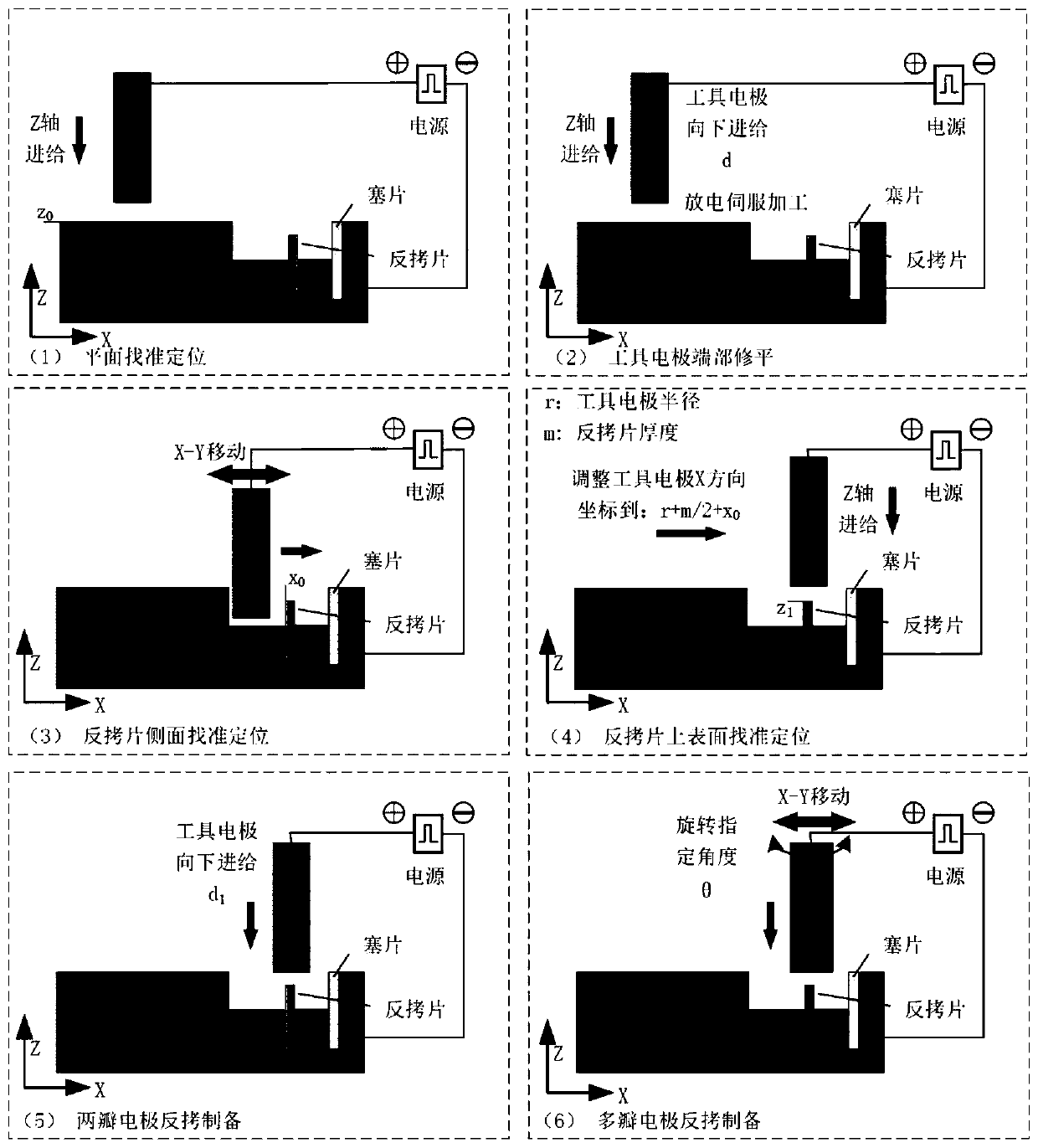
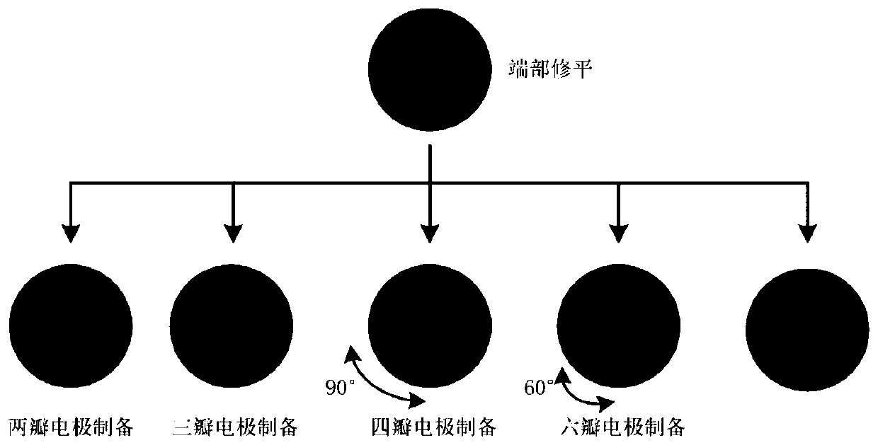
The invention provides a spark assisted chemical engraving technology of tool electrode end multiple-corner discharge constraint. A method comprises the steps that when a machining instruction is received, the positions of a reverse copying face and a reverse copying piece in an electric spark reverse copying machining device are adjusted; the end of an original tool electrode is moved according to the position of the reverse copying face so that the end of the original tool electrode can be located over the reverse copying face; the vertical movement distance of the original tool electrode isdetermined according to vertical coordinates; the end is flattened through electric spark reverse copying machining; the flattened end is controlled to move to one side of the reverse copying piece,preset electric parameters are controlled, the original tool electrode is controlled to be fed to the reverse copying piece according to the machining technological parameters, reverse copying machining of a through groove formed in the flattened end of the original tool electrode is achieved through electric spark reverse copying machining, and therefore a target tool electrode with the multi-section multi-corner end is obtained. The spark assisted chemical engraving technology of the tool electrode end multiple-corner discharge constraint can achieve tool electrode end discharge constraint and electrolyte replacement improvement, and can improve the energy utilization rate, the machining accuracy and the accuracy.

Description

technical field [0001] The invention relates to the technical field of micro special processing, in particular to a discharge-assisted chemical processing method and device based on tool electrodes. Background technique [0002] Spark Assisted Chemical Engraving (SACE for short) technology, the basic principle is to use the electrolytic formation of bubbles on the tool electrode, the high temperature and high pressure generated by the instantaneous spark discharge in the insulating bubbles, and the comprehensive physical and chemical effects in the electrolyte for material erosion. Processing can realize the processing of insulating materials such as glass, quartz and ceramics. Compared with ultrasonic machining and other processing methods, discharge-assisted chemical processing is a non-contact discharge principle processing process, which can reduce or even avoid processing defects and tool loss caused by processing force. Moreover, due to the chemical dissolution and er...

Claims


Application Information

Patent Timeline
IPC IPC(8): B23H1/00B23H11/00
CPCB23H1/00B23H11/00
Inventor 佟浩姬波林韩小凡李勇李俊杰普玉彬
Owner TSINGHUA UNIV
Learn More